Flight Basics
Objective
By the end of the laboratory the student will:
- Construct, fly, and safely recover a basic model rocket.
- Demonstrate basic rocket safety procedures.
- Demonstrate proper operation of an electronic altimeter and ground-based altitude triangulation.
- Calculate velocity and acceleration from measured altitude data and compare them with a computer model.
Before You Begin
You really should do pre-lab for this experiment.
In the evening lab you should do everything you can to prepare for the launch and especially for the data analysis. At a minimum record all of the info needed for the Flight Card, practice prepping your rocket for launch, transfer data from the altimeter to your computer, set up a spreadsheet to analyze the data, use both VIs on the data, have Rocksim or OpenRocket output for all three motors, practice with the inclinometer and the CalcHeight VI, and write up as much as possible in your lab report leaving reserved space for your results and analysis.
Plan your time well. Sections 2 and 3 will take at least 1½ hours to complete. If you're not done with Section 1 by 8 PM, assign one team member to finish the rockets and get the other members working on Sections 2 and 3.
For this lab only: We are going to let you see the grading rubric ahead of time. You should observe how the detailed instructions for the lab translate to the points awarded for the lab reports. We have similar rubrics for each lab, but we expect you to figure our what is important for each lab and allocate your time accordingly. If you are having trouble with this process, ask a proctor or professor for help.
Section 1 – Build Your Quest Quick Kit Rocket
This year the Flight Basics rocket is the Quest Seeker. There are two slightly different versions of the Seeker. The first is in a clear plastic box and has flat black body tubes and trapezoidal fins. The second is in a clear plastic bag and has gloss black body tubes and fins with a point at the front. Otherwise the two kits are identical. When you assemble the rocket there are several changes that need to be made to the plans found in the kit. Complete Steps 1, 2, and 3 as given in the printed instructions. Then follow the Seeker Addendum. Check with your proctor or professor for the latest updates. The Addendum refers to the Adept Rocketry guidelines, which are found here. Do not use the Pnut Instructions guidelines for calculating hole sizes. However, the holes should not be smaller than .050 in any case (paper is hard to drill and smaller than .050 will not work well).
You can also use the Adept Rocketry document to calculate the position of the holes, but remember that you want the holes in the same part of the payload bay as the altimeter.
In addition, you should place self adhesive decals with your section and team numbers in a clearly-visible spot on both sections of the rocket when it is finished (assuming Sam made them, otherwise a Sharpie® on a fin or the nosecone works well).
Take your time and work carefully. Ask the proctors if you have any questions.
After the rocket is assembled, place an altimeter mock-up (NOT an altimeter) in the payload section and weigh and measure the center of gravity of the rocket. You will need the measurements for Modeling and for the Flight Card.
One final note: The plastic parachute that comes with the kit will take a permanent set if stored folded up in the rocket and may not deploy properly upon ejection. It is best to store the rocket with the parachutes open and outside the rocket, even for overnight.
Additional Information: Depending on the year, there are three possible different rockets you may fly, the Seeker, the Triton-X, or the Penetrator. For each of them, there are several changes that need to be made to the plans found in the kit. Complete Steps 1, 2, and 3 as given in the printed instructions. Then follow the Seeker Addendum, the Triton-X Addendum, or the Penetrator Addendum, respectively for your given rocket. The previous-generations rocket was the Quest EZ-Payloader, which is no longer manufactured.
Section 2 – Altimeter Testing
Check out an altimeter and record its number (written in Sharpie on the altimeter). Read the altimeter instruction manual. While you are using the altimeter, use the jumper to turn the altimeter on and off. Always record the battery voltage (you'll need it for your flight card) and recharge the battery if the voltage drops below 3.90 V.
Turn the altimeter on and acquaint yourself with the series of beeps. Turn off the altimeter. Prepare the test chamber (remove the lid and squeeze the syringe all of the way down). Turn on the altimeter, place it in the test chamber, and screw on the lid. When you hear the ready beep, simulate a rocket launch by rapidly withdrawing the syringe (stop before it's all of the way out) and then slowly squeeze the syringe back in. Remove the altimeter from the test chamber. Record the peak altitude. Attach the altimeter to the computer and download the flight data. If you wish to use your own laptop, you can download either the Windows software, or the Mac OS X software. The PerfectFlite website has USB to serial drivers if you need them. Does the peak altitude correspond to that reported by the beeps?
You can compare your simulated file with a file from a real flight in the appendix below.
Data Processing
The data file from the altimeter is a text file with five columns of data: the time in seconds since the start of the file, the altitude AGL in feet, the velocity in FPS (not MPH), the altimeter temperature in °F, and the battery voltage. Open the file in a spreadsheet application.
In the spreadsheet calculate the velocity versus time and the acceleration versus time from the altitude versus time data. The velocity calculated from the data will be somewhat noisy. The acceleration calculated from the data will be very noisy.
There are two LabVIEW VIs that have been developed to help minimize numerical noise amplification from taking derivatives. The first, NumDerivLPFilt.vi, passes the data through a lowpass filter with an adjustable cutoff frequency. The second, NumDerivSplineFit.vi, uses a least-squares algorithm to fit a cubic spline (a smooth curve) to the data and then takes the derivatives of the spline. It has an adjustable parameter that controls how tightly the spline fits the data. Run both of these VIs on your data and adjust the Filter Frequency or Balance Parameter until you get the best results.
You will have to do the complete data collection and analysis process tomorrow in the field. Practice until
you can do it quickly.
You may use the actual flight data from the appendix below to test your data processing.
Extra Credit
From the standard atmospheric model (see Atmospheric Model) and the volume of the test chamber and the syringe, calculate the peak altitude you expect your altimeter to report and compare it with the actual reported altitude. Would the length of time you wait before starting the descent affect the reported peak altitude? Why? Note: no explanation of how to do these calculations will be given in lecture, but you could ask a professor.
Section 3 – Modeling
We have two programs available for you to model the rocket flight: Rocksim and Open Rocket. Rocksim is a commercial program for modeling and predicting the flights of model rockets.
We have it installed on all of the E80 computers, and you can sometimes find it on the ECF computers as well. Open Rocket is an open source Java program you can install on your own machine. They both work reasonably well, but they don't give identical results. We will model flights several times during the course, so you should become familiar with one or the other. The sim files for the Seeker are quest_seeker_hmc.rkt (with trapezoidal fins) or quest_seeker_hmc_pf.rkt (with front-pointed fins) for Rocksim, and quest_seeker_hmc.ork (with trapezoidal fins) or quest_seeker_hmc_pf.ork (with front-pointed fins) for Open Rocket. After opening the file, mark the Center of Pressure on your rocket as calculated by Rocksim or Open Rocket. Next, set the mass and center of gravity of your modeled rocket to correspond to your measurements in Section 1. For Rocksim, click on the mass override tab, and entered your measured mass and center of gravity. For Open Rocket, Select the Rocket design tab if not already selected. Then click on Sustainer in the design tree. Click on the edit button. Then check both Override mass, and Override center of gravity, and enter the values for your rocket.
For your flights you will use an Estes B4-4, an Estes B6-4, and (if you have time) a Quest B6-4. Simulate flights with all three of the given motors. If you have time you may want to simulate flights with an Estes C6-5 and a Quest C6-5 as well.
For your simulations, the ground altitude in the gravel pit is approximately 1200 feet MSL. You will need to check the weather forecast for temperature, relative humidity, and wind.
Both modeling programs are feature-rich and are not totally intuitive. Ask a proctor or professor if you need help.
After you've simulated all of your motors, export your simulation data in a format useful for Section 5.
To get a sense of how accurate the modeling programs predictions are, actual flight files for a Quest Seeker with a PerfectFlitePnut (sr=20SPS), launched at an altitude of 3000 feet, with temperatures between 38°F and 70°F are given in the appendix below.
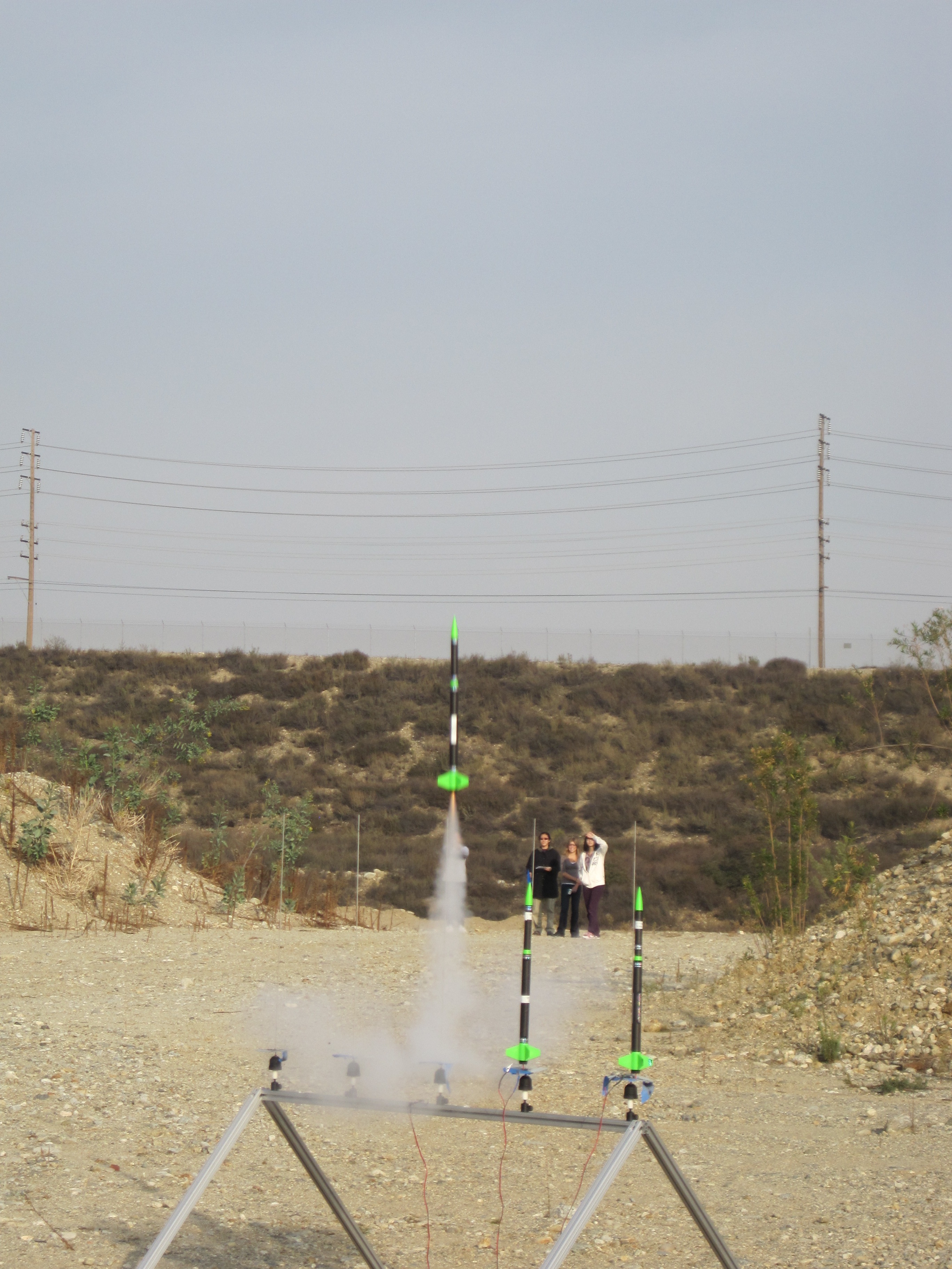
Section 4 – Flight
The launches are from the gravel pit East of the Claremont Colleges. The entrance is at the intersection of Claremont Boulevard and Arrow Route. You should practice your flight preparations and data analysis process to the extent possible during the evening lab. The time goes quickly in the field and you want to have practiced as much as possible beforehand.
Prepare your rocket for launch according to the checklist. As part of the process you'll need to fill out a Flight Card for each flight. We will have checklists and Flight Cards for you at the launch. The links are for your reference. The official Flight Cards are printed on card stock and are available at the launch or can be picked up in lab the night before. You can fill in most of the flight card before prepping the rocket, but you won't be able to fill out the Motor, the Altimeter Number, or the Altimeter Voltage until you are prepping the rocket for launch.The LCO will fill out the Pad #. Note that the nylon screws are reusable for many more launches than you are likely to make. Please don't throw them away.
Station three team members at the altitude observation points with the inclinometers.
Make note of the latitude, longitude, and altitude of the observation points and the launch stand as recorded by the proctors. A discussion of triangulation is found here.
Launch the rocket. Have the three remote team members record the azimuth and elevation angles of the rocket at apogee at each of the observation points.
Recover both sections of the rocket. Return to the computer station and download the altitude data. Save them in an appropriate location. Be sure to name the file according to the following naming convention:
- Rocket type (QS, QT, or QP),
- Motor designation with Q for Quest, no letter for Estes, e.g., B4-4, or QB6-4,
- S followed by section number,
- T followed by team number,
- F followed by flight number (for your team),
- Underscore then date in YYYYMMDD format.
The file should end up with the .pf2 extension. For example, if Team 2 of Section 3 flew their Quest Seeker rocket for their third flight on an Estes B6-4 on January 29, 2015, the file name would be QSB6-4S3T2F3_20150129.pf2
You may want to make a back-up or two.
Be sure to submit a copy of your files to Sakai in the Flight Data folder inside Resources.
You are required to fly at least two (2) flights, one on an Estes B4-4, and one on an Estes B6-4. If you have time, you may (should really want to) make one additional flight on a Quest B6-4.
Section 5 – Data Processing
The data file from the altimeter is a text file with five columns of data: the time in seconds since the start of the file, the altitude AGL in feet, the velocity in FPS (not MPH), the altimeter temperature in °F, and the battery voltage. Open the file in a spreadsheet application. Compare the peak altitude with that calculated from the inclinometer data. You can either analyze the inclinometer data by hand or use the VI CalcHeight64.vi. There are two different versions of the CalcHeight VI: CalcHeight64.vi, that works with the 64-bit version of LabVIEW that is currently installed on the E80 lab computers, and CalcHeight.vi, that works with the 32-bit version of LabVIEW. Comment on all of your results paying close attention to errors, error estimates, and noise.
In the spreadsheet calculate the velocity versus time and the acceleration versus time from the altitude-versus-time data. Compare all three: altitude, velocity, and acceleration versus time with your Rocksim results (we shouldn't have to point this fact out, and we won't in the future. The best way to do the comparison is with a properly labeled graph comparing the measured and modeled data on the same graph). Comment on the comparison paying close attention to errors, error estimates, and noise.
There are two LabVIEW VIs that have been developed to help minimize numerical noise amplification from taking derivatives. The first, NumDerivLPFilt.vi, passes the data through a lowpass filter with an adjustable cutoff frequency. The second, NumDerivSplineFit.vi, uses a least-squares algorithm to fit a cubic spline (a smooth curve) to the data and then takes the derivatives of the spline. It has an adjustable parameter that controls how tightly the spline fits the data. Run both of these VIs on your data and adjust the Filter Frequency or Balance Parameter until you get the best results. Comment on how these results compare with the Rocksim results and your spreadsheet results.
Note: you can right-click on the VI graph and copy the data to be pasted into a spreadsheet.
Appendix – Rocket Data
All three rockets (Penetrator, Triton-X, Seeker) were flown on a series of test flights. The altitude data were recorded using a Pnut altimeter (sr = 20 SPS). An Excel spreadsheet with the data and plots for all three rockets is found here.
The individual files flight files and other rocket info are given in the table below.
These files can be used to test out the VIs and your data processing routines. For your enjoyment, here is a data file from a high-performance rocket taken using a Pnut. The apogee was 6675 ft AGL.
In addition all three rockets (Penetrator, Triton-X, Seeker) were flown on test flights in preparation for the class using the now-obsolete Alt15K/rev2 altimeter (sr = 10 SPS). An Excel spreadsheet with the data and plots for all three rockets is found here.
The individual files flight files and other rocket info are given in the table below.
*The Alt15k requires the rocket to go at least 100 feet before it registers lift-off. The Penetrator made it about 80 feet.
If you want to use the flight data from these obsolete files, you can use the versions of the VIs for the Alt15k Altimeter: NumDerivLPFiltAlt15k.vi and NumDerivSplineFitAlt15k.vi respectively.