Basic Electrical Measurements
Objectives
By the end of the laboratory the student will:
- Demonstrate the proper use of a digital multimeter, an oscilloscope, a signal generator, and a computer-based Data Acquisition system (DAQ) in performing basic electrical measurements.
- Demonstrate and explain the effects of instrument loading (impedance) on basic electrical measurements.
- Calculate the uncertainty in a measurement based on the uncertainties in the components used to make the measurements.
- Demonstrate theoretical and practical usage of a voltage divider.
- Demonstrate the practical usage of a unity-gain buffer amplifier.
Before You Begin
This lab will be done in sub-teams of two or three. Plan your time and workload accordingly. Bring your protoboard!
You will need to use a myDAQ during the lab. We will have one for each sub-team to use, but we strongly recommend that you buy your own (with LabVIEW, Multisim, & Ultiboard, 781327-01). Either way, we strongly recommend that you install the Student Version of LabVIEW and the myDAQ software on the computer you plan to use before you get to lab. While LabVIEW runs on Linux and OS X, the myDAQ driver is Windows only. The software can take up to an hour to install, and you really don't have an hour to waste on software installation during lab.
For Sections1 through 4 of the lab, you will need to have the DMM on the myDAQ functioning correctly. The later sections require some additional myDAQ instruments. To use the myDAQ DMM, connect the myDAQ to the computer using a USB cable, insert the DMM Banana Cables into the COM and V,Ω, jacks, start the NI ELVISmx Instrument Launcher, click on the DMM, set the mode to Auto, and click on the RUN button.
It wouldn't hurt to read or review Auntie Spark's Guide to breadboards and Uncle Sparky's guide to Voltage, Current, and Resistance Measurements.
Percentage Indications: This lab has percentage indications by each section. These percentages indicate roughly what fraction of the lab time you should spend on each section. Sections 1, 2, & 3 are prelude to being able to do Sections 4 through 7. The percentages also roughly correspond to what we're looking for in the grading. We still expect you to use the guidelines shown in the Course Info on Laboratory Report Guidelines, keeping in mind the line that says "Depending on the order of steps in an experiment, you may need to select a different format, however, the outline is provided as a general example of good practice." Succeeding labs will not have these percentage indications. We expect you to figure out what is important and where you should focus your effort. Ask a proctor or a professor when in doubt.
Section 2 (10%)
We strongly recommend that you only use the waveform generator in the oscilloscope and not the stand-alone signal generator. However, we have the instructions for both instruments in this section. The purpose of this section is to determine the purpose of the Output Load setting on the Oscilloscope Signal Generator and/or the OUT TERM setting on the signal generator. They both behave in exactly the same way, and used incorrectly, you will find a factor of 2 or 1/2 in your measurements that you can't explain.
For the Oscilloscope Waveform Generator:
- Turn on the oscilloscope.
- Set the waveform generator by pushing the Wave Gen button.
- Push the button below the displayed Settings menu.
- Set the Output Load to High-Z (it may already be set to High-Z).
- Push the Wave Gen button again.
- Set the Frequency to 200 Hz
- Set the Amplitude to
1.5VPP.
- Set the offset to 0.00 V.
For the Stand-Alone Function Generator:
- Turn on the oscilloscope.
- Turn on the signal generator.
- Set the “OUT TERM” of the signal generator to “High Z” by following the steps shown below (Keep the rest in default settings).
The signal generator may already be set to "High Z."
| Press |
Shift |
|
|
| Press |
Enter |
display shows: |
A:MOD MENU |
| Press |
> |
display shows: |
B:SWP MENU |
| Press |
> |
display shows: |
C: EDIT MENU |
| Press |
> |
display shows: |
D: SYS MENU |
| Press |
V |
display shows: |
1: OUT TERM |
| Press |
V |
display shows: |
50 OHM |
| Press |
> |
display shows: |
HIGH Z |
| Press |
Enter |
|
|
- Press “Ampl” and set the amplitude to 1.5VPP.
- Adjust the frequency to 200 Hz.
- Adjust the offset to 0.00 V.
Questions
- What is the amplitude of the sine wave as measured by the myDAQ DMM, Elenco, and ’scope? What are the relationships among the amplitude displayed on the signal generator and the amplitudes displayed by the meters and scope? Are the measurement accuracies within the manufacture specifications?
- Do not adjust the amplitude (don't turn any of the knobs or push any of the buttons that affect amplitude), but reset "Output Load" to "50 Ω" or “OUT TERM” to “50 OHM,” record the VPP displayed on the oscilloscope waveform generator or stand-alone function generator and repeat your measurements with the Elenco and ’scope. What are the relationships among the amplitude displayed on the waveform or function generator and the amplitude displayed by the meter and ’scope?
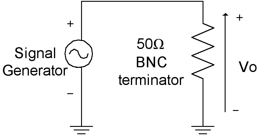
- Measure and record the resistance of a 50 Ohm BNC Terminator. It should be close to the nominal 50 Ω.
- Keep the waveform or function generator settings as those in (b). Connect its output signal to a 50 Ohm BNC Terminator as shown. A BNC Tee makes the connection fairly trivial. Measure the voltage V0 across the terminator with the Elenco and scope. Explain the purpose of the "Output Load" or “OUT TERM” setting. Confirm your explanation with a professor or proctor.
Section 2A
Remove the 50 Ohm terminator. Reset the Output Load or OUT TERM to High-Z. How do the accuracy of the myDAQ DMM, and Elenco vary as you adjust the frequency to 100 Hz, 200 Hz, 500 Hz, 1000 Hz, 5000 Hz, and 10,000 Hz?
Section 3 (5%)
Oscilloscope probes
come typically with two settings: 1X and 10X. Oscilloscopes usually permit you to enter the setting of the probe you are currently using. Our scopes permit you to enter any setting (in a 2, 5, 10 order) from 0.1X to 100X. We recommend you normally use the grayish probes kept in the drawer beneath the work surface. They are 10X probes and can't be set to any other setting. However, for this section, find one of the black probes that can be switched between 1X and 10X.
- Measure (don't just look it up) and record the DC impedance (the resistance) of the scope probes on both 1X and 10X settings, and then do parts b through d. Don't measure the scope impedance. You looked it up for Section 1.
- (Calculate) What is the input impedance of the scope (meaning the scope and probe together, not just the probe by itself) when the probe is on the 1X setting?
- (Calculate) What is the input impedance of the scope (meaning the scope and probe together, not just the probe by itself) when the probe is on the 10X setting?
- Does the 10X setting have any effect on the measured voltage? Why*?
Unless you have a very specific need to do something else, always make oscilloscope measurements with a 10X scope probe, and with the scope set for the 10X probe. To enter the probe setting, push the channel button for the channel you're using, e.g., push the (1) button for channel 1. Then push the button below the Probe menu item. Rotate the settings knob until the desired setting (almost always 10X) is displayed and push the settings knob.
*In the past we have not explained the intent of the question. This one time we will explain it. You probably did not suspect it but we have carefully led you to determine that the oscilloscope and the 10X probe together form a voltage divider without telling you what it is. For a voltage divider you should be able to calculate the impedance of the whole divider from the values of the two components and what the output voltage should be relative to the input. The answers to b, c, and d, are quantitative and have precise (with uncertainty) answers. We expect you to calculate these answers from your measurements and tech manual look-ups and compare them with what you measure on the scope. The agreement should be very good. In the future (and the past) we will not be so explicit. We expect you to figure things out and/or ask the proctors or professors if you are unsure.
Section 4 (15%)
The 100kΩ thermistor is a Vishay NTCLE100E3104JB0 (Digikey P/N BC2302-ND) Read the data sheet on the 100kΩ thermistor and determine the formula to calculate the temperature from the resistance. Also determine the error specifications for the thermistor and the myDAQ DMM Ohm settings. Measure the resistance of the thermistor (it's probably best not to touch the thermistor or the leads with your fingers (why?), and calculate the room temperature from the measured resistance complete with propagation of errors to calculate the uncertainty. If the data sheet disagrees with the class notes, use the data sheet. Compare you calculated temperature with the room temperature measured by one of the digital thermometers. Do the measurements agree within the uncertainty of the measurements?
Section 5 (30%)
For this section you will use both the myDAQ DMM and the myDAQ Oscilloscope. If your computer is fast enough you can run both at the same time. Make note that the inputs to the myDAQ Oscilloscope are AI0 and AI1, not the banana plug cables for the DMM.
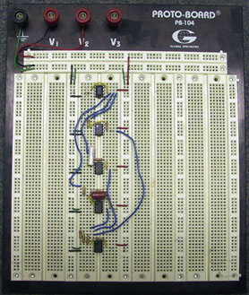
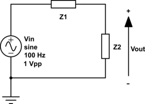
Build the circuit shown in the figure on your own protoboard. You might find it convenient to build all the circuits at once, neatly on your protoboard, but don't connect any of them to the power busses or each other (why not?). You can then move the voltage input and ground and the measurement probes from one circuit to the next and cycle through the measurements quickly. Trim the resistors with wire cutters so they lay neatly on the protoboard. Given the following circuit with impedances, predict the output voltage for each case from (A) to (D).
The output-voltage predictions can (should) be done as prelab.
| Case |
Z1 |
Z2 |
Measure With |
| (A) |
10Ω |
20Ω |
Elenco, myDAQ DMM, myDAQ 'Scope |
| (B) |
1kΩ |
2kΩ |
Elenco, Scope 1X, myDAQ Scope |
| (C) |
100kΩ |
200kΩ |
Elenco, Scope 1X, myDAQ Scope |
| (D) |
10MΩ |
20MΩ |
Elenco, Scope 1X, Scope 10X, myDAQ DMM, myDAQ Scope |
Use the signal generator for Vin and set it to 1VPP @ 100 Hz. After setting it, but before connecting it to any of the circuits, measure and record Vin with the Elenco, Scope 1X, Scope 10X, the myDAQ DMM, and the myDAQ Scope. Then, measure the Vout for each of the circuits in sequence with (a minimum of) the indicated instruments starting from case (A), and compare the measurement results with your predictions . Explain your results (especially any surprises). Sketches of equivalent circuits with analyses are often useful in explanations.
If Case (D) is giving you problems, try just twisting the components together and measuring things off of the protoboard. The leakage current is fairly high on the protoboard and it may interfere with your measurements.
Section 6 (15%)
Read the notes on op-amps below and/or Auntie Spark's Guide to Op-Amp Circuits. Replace the circuit in Case (A) of Section 5 on your breadboard with the following circuit and repeat your measurements.
Power the op-amp with ±15 V.
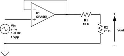
Compare and contrast your results from Case (A) with your current results. What is the function of the op-amp?
Note: The OPA551 has a thermal limiting circuit internal to the device. If you draw too much current the device will shut off until it cools down. It will then turn back on. If your OPA551 is behaving strangely (turning on and off or showing a glitch pulse periodically) it is not broken. You are drawing too much current from the device. Don't dispose of it and get another. Figure out how to reduce your current draw, e.g., reduce your input voltage.
Section 7 (15%)
Replace the circuit in Case (D) of Section 5 on your breadboard with the following circuit and repeat your measurements.
Power the op-amp with ±15 V.
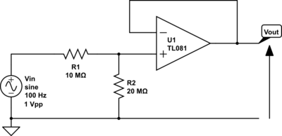
Compare and contrast your results from Case (D) with your current results. What is the function of the op-amp?
Extra Credit
- Replace Z2 in Case (C) of Section 5 on your breadboard with the 100Ωk thermistor and derive a formula to calculate the temperature from Vin and Vout. Also determine the error specifications for all of the components in your system. Measure Vin and Vout with the myDAQ Scope (it's probably best not to touch the thermistor or the leads with your fingers (why?), and calculate the room temperature from the measured Vin and Vout complete with propagation of errors to calculate the uncertainty. Measure the actual resistance of Z1 (yes, Z1, not Z2. You're calculating the resistance of Z2 in the experiment, but you need the value of Z1 to do it) with the Elenco and repeat the measurement and calculation. How much did the uncertainty change? Compare you calculated temperatures with the room temperature measured by one of the digital thermometers. Do the measurements agree within the uncertainty of the measurements? Why would you use the voltage divider circuit with a DAQ or data logger instead of simply measuring the resistance of the thermistor (say, for example, on a rocket)? In your answer you may also want to explain how the Elenco measures resistance. For your circuit explore how the measured temperature changes with Vin as you vary from 1VPP to the maximum the signal generator can generate. Why does it change?
- For the same circuit as in Section 5 repeat the predictions and measurements (You may use whatever instrument you like, including the myDAQ Bode Analyzer, but justify your choice) for the following cases from (E) to (H), where Vin= 5VPP sinusoids @ 1Hz, 10Hz, 100Hz, 1kHz, 10kHz and (if possible) 100kHz respectively. Where possible also measure the phase difference between the input and output voltages. Explain the results of your measurements and possible function for each circuit.
Consider carefully in what (graphical) format(s) you want to present your results.
Repeat the measurements with the myDAQ Bode Analyzer. Read the instructions carefully. The myDAQ replaces the signal generator and has to read both the input and output. Set the Start Frequency to 1Hz, and the Stop Frequency to 10kHz. Set the Peak Amplitude to 5V, and the Op-Amp Signal Polarity to Normal. You may need to connect AI0– and AI1– to AGND
| Case |
Z1 |
Z2 |
| (E) |
10kΩ |
0.47µF |
| (F) |
0.47µF |
10kΩ |
| (G) |
220Ω |
1µF |
| (H) |
10MΩ |
1000pF (1nF) |
Op-Amp Fundamentals
- Neatly laid out protoboards work better. Seriously, they do. They're easier to troubleshoot as well. Seriously, they are! Please take the time to do it right.
- Keep your leads short and close to the board.
- Strip off the minimum amount of insulation to let your patch wire work; Don't have big bare areas that can touch other things and short.
- Trim your resistors and capacitors to keep the components close to the boards. Don't leave the leads long. Get the components down by the board.
- Use the long busses for power only. Do use them for power and ground. Don't use them for signals. Use bypass capacitors (see below) on your power busses.
- To the extent possible use coaxial cables to get signals on and off of your board. Put the input signals onto the board as close to the circuit inputs as possible. For example, use a coaxial cable with BNC connectors from the signal generator and then put spring-loaded mini-clips on the other end. Connect the mini clips to your circuit input and ground.
- If your are using dual supplies for your op-amps, have three power busses: V+ connected to the +20V output on your power supply, V– connected to the –20V output on your power supply, and GND connected to the COM output on the power supply. You can adjust your supply voltage to be anything from ±1V to ±15V depending on what chips you are using.
- If your are using a single supply for your op-amps, have two power busses: V+ connected to the +20V output on your power supply, and GND connected to the COM output on the power supply. You can adjust your supply voltage to be anything from +1V to +15V depending on what chips you are using.
- Color code your wiring. A common practice is to use red for V+ power, black for V– power, green for ground, and white or blue for signal lines. If you have a rat's nest of all red wires, neither the professors nor the proctors (nor you for that matter) will be able to figure out what goes where.
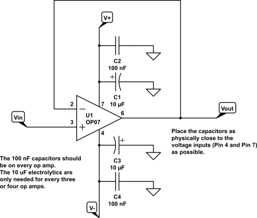
In standard practice, op-amps are shown in schematics without the power connections. However, you must supply power to the power pins or the op-amps won't work! For reference, the circuit below shows the power connected to the op-amp.
Because operational amplifiers have such high gain, if the power busses are long, the op-amps may interact with the busses and cause oscillations. The circuit works one day and is filled with noise the next. You can almost totally eliminate this issue by placing bypass capacitors between the power supply pins and ground as close as physically possible to each op-amp. Standard practice recommends both a 10 µF electrolytic capacitor and a 0.1 µF standard capacitor. For E80 just the 0.1 µF standard capacitor will suffice. If you use the electrolytic capacitors, remember that they are polar and if you put them in backwards they won't work. For dual supplies the capacitors run between V+ and ground, and V– and ground. For single-sided supplies, they run between V+ and ground. The circuit below shows a unity-gain buffer amp with dual power supplies and bypass capacitors.