Static Motor Tests and Flight Modeling
Objective
By the end of the laboratory the student will:
- Measure the thrust curves, mass flow rate of combustion gases and specific impulse for two rocket motors.
- Construct analytical and 1-D and 2-D numerical models of rocket flight..
- Compare the analytical and numerical models with the output of RockSim or OpenRocket..
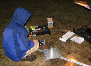
Videos of the static tests are available here.
Section 1 – Measurement of The Thrust Curve
The currently-designated site for static testing the motors is Linde Field. You will need to get all of the equipment to Linde Field and follow all safety precautions for the tests.
The list of motors scheduled for your team is found here.
There may be last minute changes in the schedule. Check with the proctor when you get to lab.
Safety Precautions
- Safety goggles are to be used by the entire team while loading and removing motors, and during the actual test.
- A square area of 60 feet by 60 feet for tests of F and G motors or 200 feet by 200 feet for H and I motors is to be marked off as a safety zone with the cones and (if possible) the safety tape. Team members and E80 staff may only enter the area when the key is removed from the safety interlock. No-one else is permitted inside the safety zone at any time.
- Make certain that there are no flammable objects inside the safety zone.
- The motors will be hot after use. Use gloves or other means to avoid being burned.
- A public announcement must be made when arming the system with the key switch that the system is being armed.
- An audible countdown must be made (5-4-3-2-1) before ignition.
- If the motor doesn't ignite or the igniter burns through wait a full minute before entering the safety zone (yes, I know it seems like forever).
Procedure
- Have a proctor or professor assemble two test motors for you.
- Some motors have already been assembled. Others will be assembled during the lab. If the motor is being assembled, during the assembly, weigh the propellant grains and the delay charges. Also measure the dimensions, I.D., O.D., and length of the propellant grains, and the O.D. and length of the delay grain for both motors. Be sure to record which motor is in which casing. If it's been pre-assembled, only weigh the motor.
- Without inserting anything into the nozzle, measure the throat diameter and exit diameter on all your motors.
- For all motors, make sure you record the weight of the completed motors without the igniter or red end cap.
- Determine from the published thrust curves whether you will need the 20 kg load cell, the 50 kg load cell, or both (The packing checklist contains a subtle hint). Verify your choice with a proctor or professor. Exceeding the rating on a load cell will destroy it. Choose the weights you will need to calibrate the load cells. Weigh the calibration rods and the calibration weights. Check the weight limit of the scale you are using and do not exceed it.
- Test and verify that the laptop computer you are taking to the test site is charged, has the VIs you require, is communicating with the chosen DAQ, and that the load cell functions properly with the DAQ.
- Transport everything on the checklist to the test site. Images of most objects on the checklist are available in the Appendix.
- Mark off the safety zone.
- Set up the test stand in the center of the safety zone. Make sure the safety key is out of the key switch before allowing anyone in the safety zone.
- Run the cables to outside the safety zone and make all needed connections. Check with a professor or proctor as to exactly what connects to what. The DAQ varies according to what is currently working. The preferred DAQ is an NI cDAQ-9171 plus NI 9237. Consult with a professor or proctor if the preferred DAQ is not working or unavailable.
- Check that the load cell is working with CheckLoadCell.vi. Calibrate the load cell with the standard weights. Please record the order in which you are going to use the weights and use the same order for the pre and post-calibration. It makes post-processing much easier. You can make use of the StaticTestAcquire.vi or your own VIs or Matlab scripts. Enter the file name BEFORE running the VI. Be sure to use the file-naming convention given below for your calibration files.
- Load and secure the first of your motors. Insert and connect the igniter to the alligator clips and check continuity. You are wearing your safety goggles, right?
- Guarantee that the data acquisition system is functioning properly. You may use StaticTestAcquire.vi or your own VIs or Matlab scripts. Enter the file name BEFORE running the VI. Be sure to use the file-naming convention given below for your test files.
- Announce and arm the system with the key switch.
- Countdown and ignite the motor.
- Make sure you have your data. You may want to make a back-up copy.
- Repeat steps 12 through 16 for the remaining motor.
- Calibrate the load cells with the standard weights.
- Weigh the used motor casings.
- Important: After weighing, remove the spent motors from the motor casings and thoroughly clean the mortor casing pieces inside and out with baby wipes.
Please put copies of the calibration and thrust data files in the Static Test Files folder in the Sakai resource folder. We have a repository of all of the thrust-curve data and we want to add yours to the collection.
File Naming Convention
- Motor designation, e.g., F37W-M, or Cal20 or Cal50 for Calibration of the 20 kg load cell or the 50 kg load cell
- S followed by section number,
- T followed by team number,
- R followed by the specific motor or cal run number for your team, e.g., the pre-calibration is R1 and the post-calibration is R2. If you only test one of a specific motor the run is R1.
- Underscore then date in YYYYMMDD format.
The file should end up with the .tdms extension (which LabVIEW normally adds automatically). For example, if Team 2 of Section 3 first calibrated their 20 kg load cell, then static tested two F37W-M motors and a G61W-M motor, then post-calibrated their 20 kg load cell, then installed and calibrated their 50 kg load cell, tested a I357T-M motor, and then post-calibrated their 50 kg load cell on March 5, 2014, they would have created the following files in the following order:
- Cal20S3T2R1_20140305.tdms
- F37W-MS3T2R1_20140305.tdms.
- F37W-MS3T2R2_20140305.tdms.
- G61W-MS3T2R1_20140305.tdms.
- Cal20S3T2R2_20140305.tdms
- Cal50S3T2R1_20140305.tdms
- I357T-MS3T2R1_20140305.tdms.
- Cal50S3T2R2_20140305.tdms
The VI StaticTestFileRead.vi is useful in analyzing the calibration and static test files. It has the ability to select a given region of a file and calculate the average value and the integral for that range.
If you forgot to rename the file for each run, you may have to read different groups in your file. The VI StaticTestFileReadMultiRun.vi can be used to find the missing runs.
Section 2 – Motor Performance Specifications
The instructions for the remainder of this lab are not as detailed as for some of the earlier labs. You are expected to plan out your experiments and fill in the blanks. Ask a proctor or professor for help if you can't figure out what to do.
For each of your tested motors and your measured and/or recorded data plot the thrust curve and compare it with either the manufacturer's published curve or the one on thrustcurve.org, then:
- Calculate the total impulse.
- Calculate the average thrust and average mass flow rate.
- Calculate the exit velocity of the combustion gases from the nozzle. What assumptions did you have to make?
- Calculate the specific impulse, Isp.
Section 3 – Analytic Flight Model
Develop an analytical (not numerical) model and estimate the maximum height reached for the rocket described below.
- Rocket mass = 964g
- Average thrust = 80 N
- Burn time = 1 s
- Rocket body diameter for calculation of projected area = 4.83 cm
- Average CD = 0.57
- Average air density = 1.15 kg/m3
Discuss the validity of the assumption of constant thrust over the burn time.
You may find the following integrals helpful:
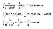
You may also find this link helpful.
Section 4 – Numerical Methods
- Develop and implement a 1-DOF numerical model to integrate the equations of motion for the rocket flight from liftoff to apogee. Input variables should include time step; parameters associated with the different rockets available for launch; and parameters associated with the motors you tested. You may also use thrust curve data from the Class Thrust Curves or the thrust curves included with the motors. The outputs of the model should include global vertical position, velocity, and acceleration predictions, as well as maximum altitude reached by the rocket. How much of a difference does drag make in the model? You can double check your model with the solutions to Section 5 of the Wind Tunnel lab and Section 3 of this lab.
- (Don't spend too much time on this step, and plan your debugging carefully) Develop and implement a 3-DOF numerical model to integrate the equations of motion for the rocket flight from liftoff to apogee. Input variables should include time step; side wind magnitude; parameters associated with the different rockets available for launch; and parameters associated with the available motors (you may use thrust curve data from the Class Thrust Curves or the thrust curves included with the motors. The outputs of the model should include global position, velocity, and acceleration predictions, as well as maximum altitude reached by the rocket. How much of a difference does drag make in the model?
- Test your models for either the Aerotech Arreaux or Aerotech Barracuda rocket, with a either a constant coefficient of drag of 0.57 or one you obtained in the Wind Tunnel or from RockSim or OpenRocket (which may vary with velocity, check under Rocket->CD analysis), a constant side wind magnitude of 3 mph (if applicable), use the two motors you tested or use the first G79W-M motor from 3/8/2008, and time steps of 0.5, 0.05, and 0.005 seconds. Plot the trajectory and predict the maximum altitude of the rocket. You may want to look at the RockSim or OpenRocket model ( aerotech_arreaux.rkt or aerotech_barracuda.rkt for RockSim and aerotech_arreaux.ork or aerotech_barracuda.ork for OpenRocket.) to get dimensions, mass, center of mass, and center of pressure data for the rocket. The models that come with RockSim are in Program Files\RockSim\Designs.
You may use any numerical tool you desire for your modeling, such as LabVIEW, MATLAB, Mathematica, or a spreadsheet. If you choose LabVIEW, there are four Vis available to get you started:
- ReadThrustCurve.vi will read a thrust-curve file and create LabVIEW arrays with the information. It is required by the other VIs.
- Get Thrust Array.vi takes an input of an array of strictly-increasing time values and returns an array of the thrust values from a given thrust curve at the times.
- SampleThrustCurve.vi takes a desired sample rate as an input and returns an array of time values starting at 0 and spaced at the sample rate, and an array of thrust values at those times.
- 1DsimNoDragOrWind.vi is a 1-D explicit Euler simulation of a rocket in the Earth's gravitational field being powered by a chosen motor, and experiencing no drag or forces other than thrust and gravity. It terminates at the earlier of the chosen end time or when the rocket returns to an altitude of 0. It requires both ReadThrustCurve.vi and SampleThrustCurve.vi.
- 1DsimNoDoWForm.vi is also a 1-D explicit Euler simulation of a rocket in the Earth's gravitational field being powered by a chosen motor, and experiencing no drag or forces other than thrust and gravity. The difference is that it uses a formula node for calculating each time step rather than LabVIEW functions. Some students find it easier to understand. It terminates at the earlier of the chosen end time or when the rocket returns to an altitude of 0. It requires both ReadThrustCurve.vi and SampleThrustCurve.vi.
To use your own data files with these VIs your data files must be in the following format: 4 lines of text information, 1 line of column labels (including the word "Newtons" if you want the results to indicate Newtons instead of pounds), your data in tab-delimited format with time in seconds in the first column, and force in the second column. See one of the existing Thrust Curve files for an example of the format
Section 5 – RockSim or OpenRocket
- Using the simulation software RockSim or OpenRocket, predict the performance of either the Aerotech Arreaux or Aerotech Barracuda rocket launched with the motors you tested or a G79W motor and a constant side wind magnitude of 3 mph. Compare the RockSim or OpenRocket predictions to your prediction from Section 4 (c).
- Discuss the differences, if any, between the predictions.
- A list of motors that will be available in the motor lottery/draft for the final project is located here. Feel free to use this list in any way you see fit.
- Why did we make you do this experiment?
Appendix – Illustrated Case Loading Procedure (click on the step to see the illustration)
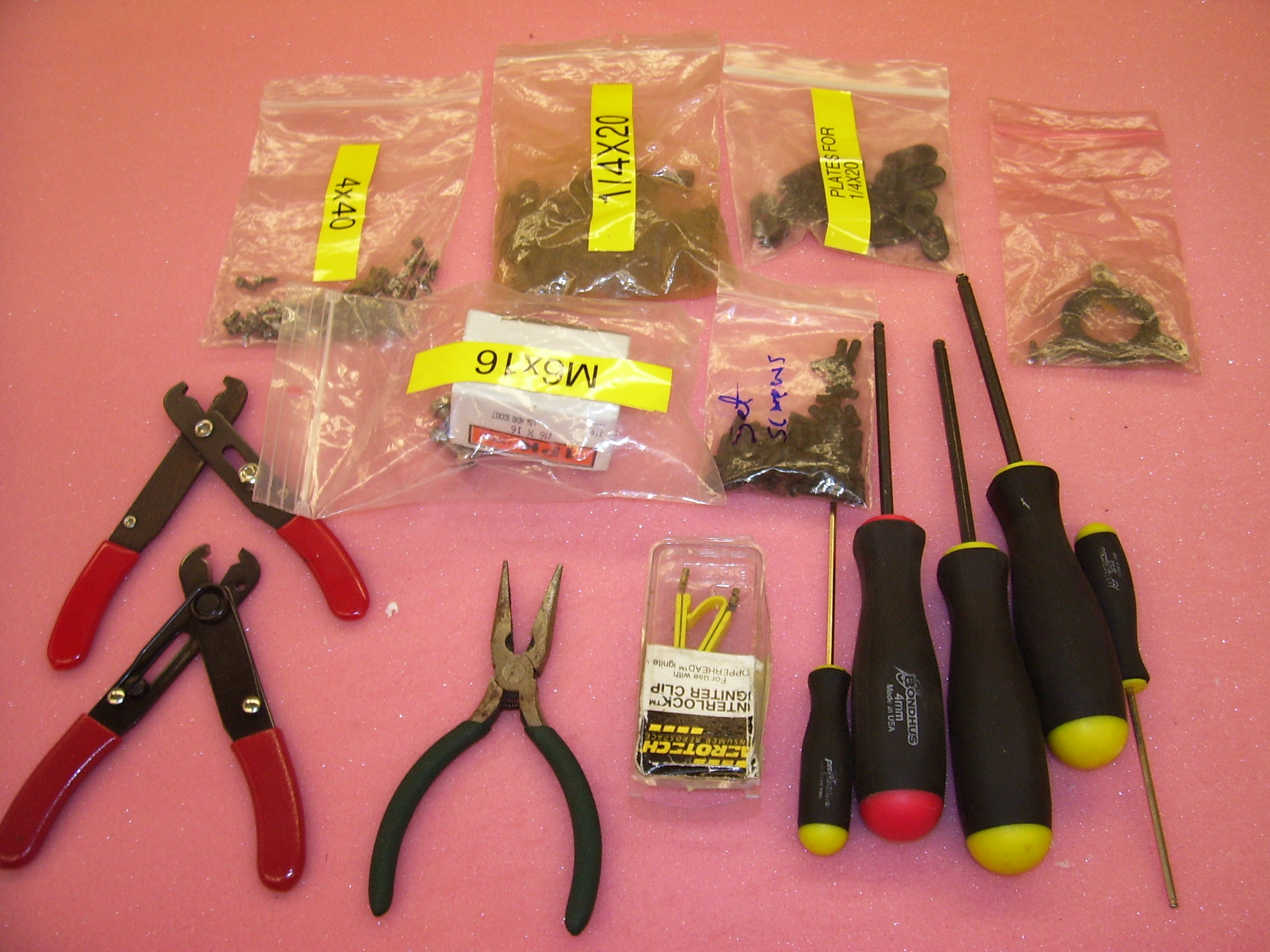
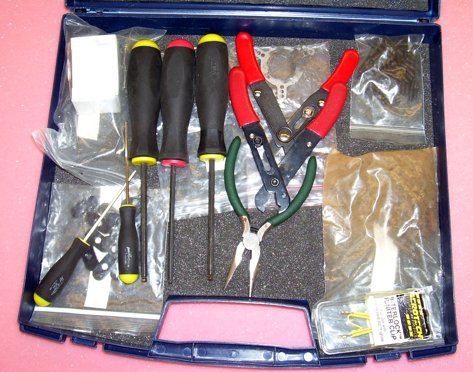
Toolbox
- Verify that you have all of the tools and supplies.
- Load all in the toolbox and close the case.
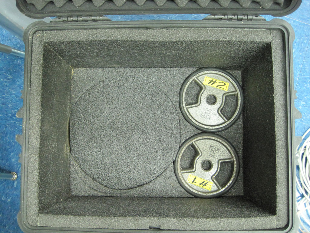
Case 1
- Load weights #1 and #2.
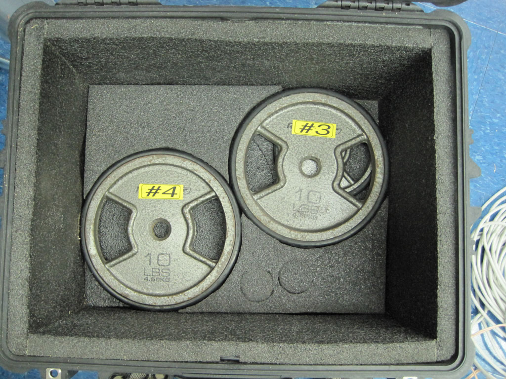
- Load weights #3 and #4.
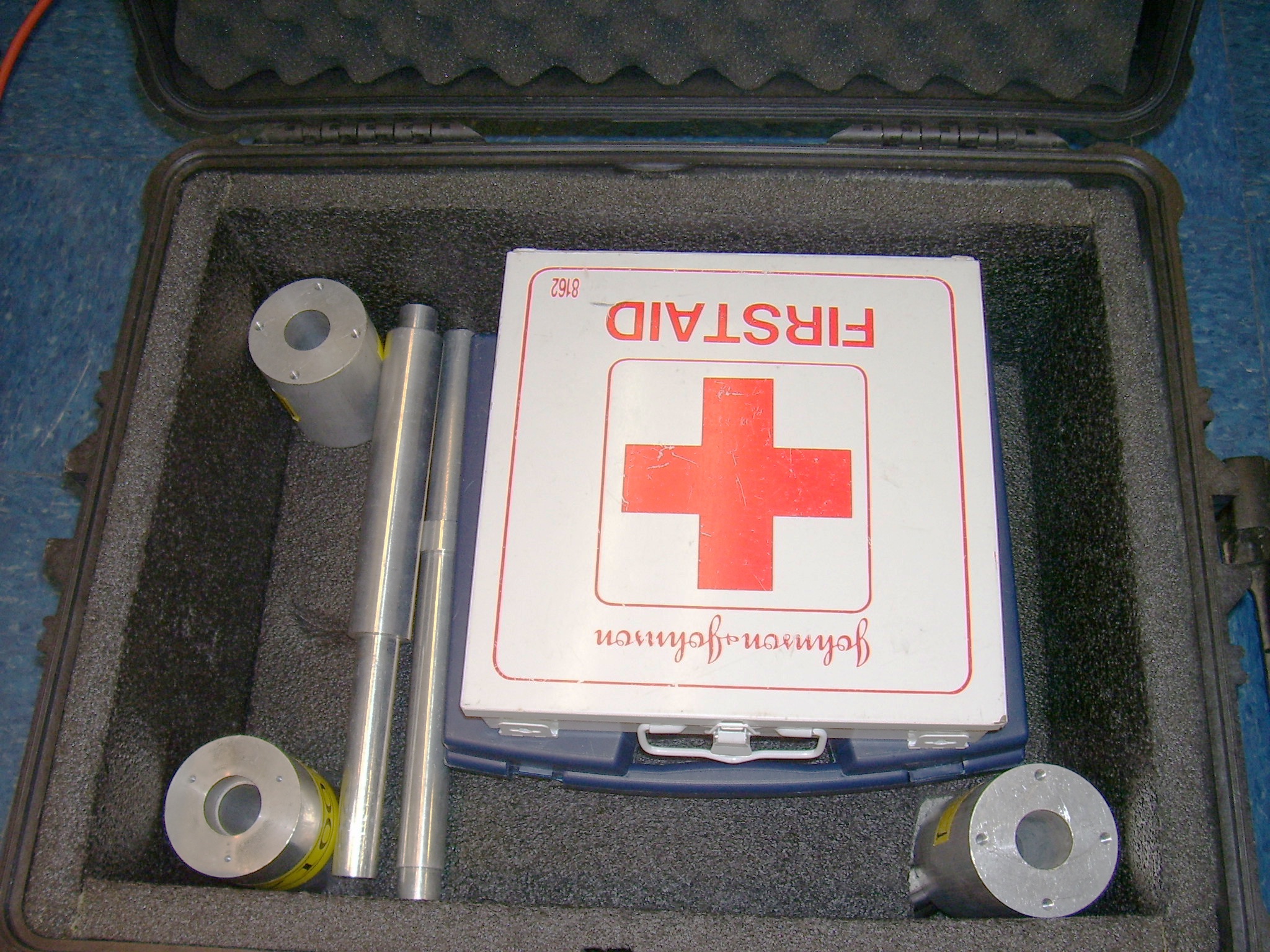
- Load toolbox, motor holders, calibration rods, and first aid kit.
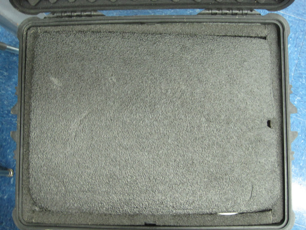
- Cover with foam and close and lock lid.
Case 2
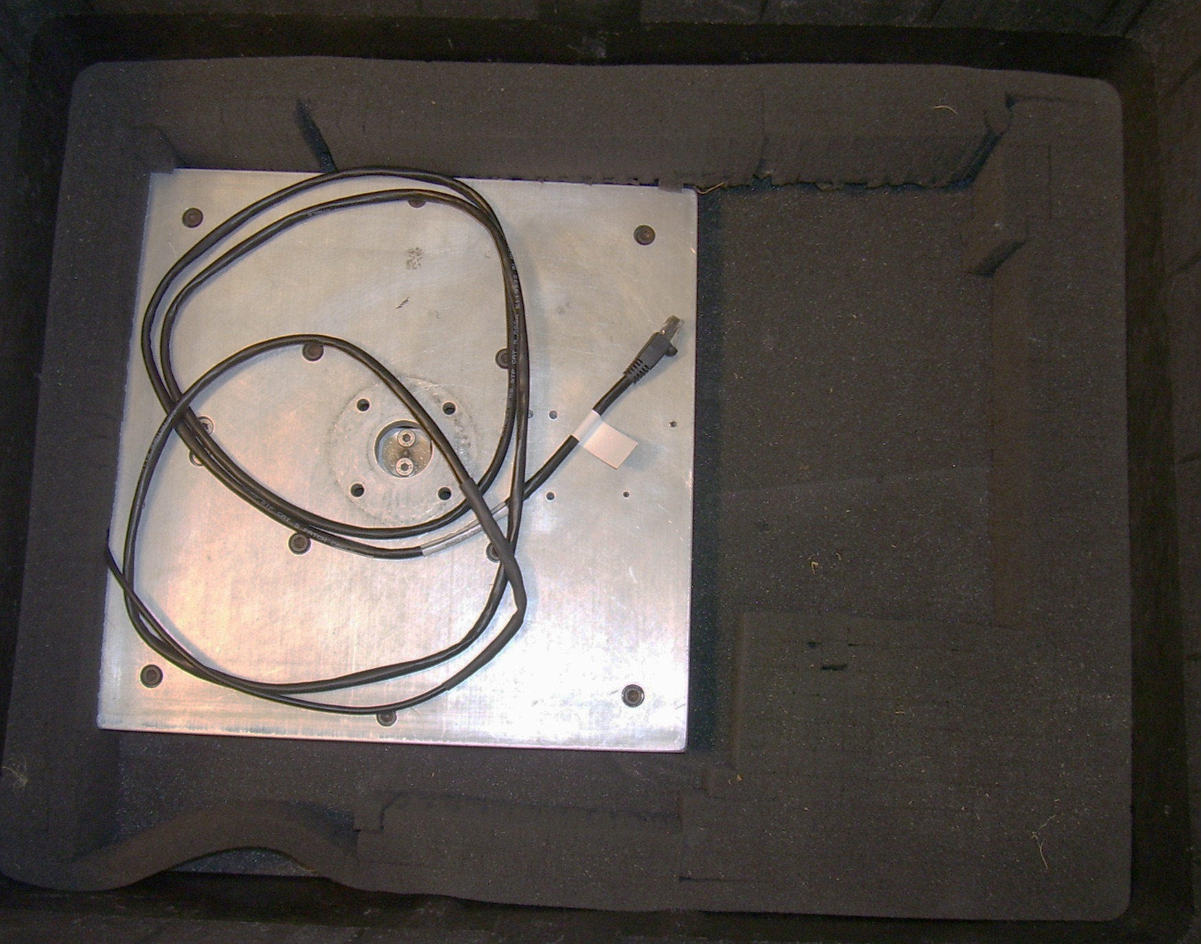
- Load test platform with 20 kg load cell attached.
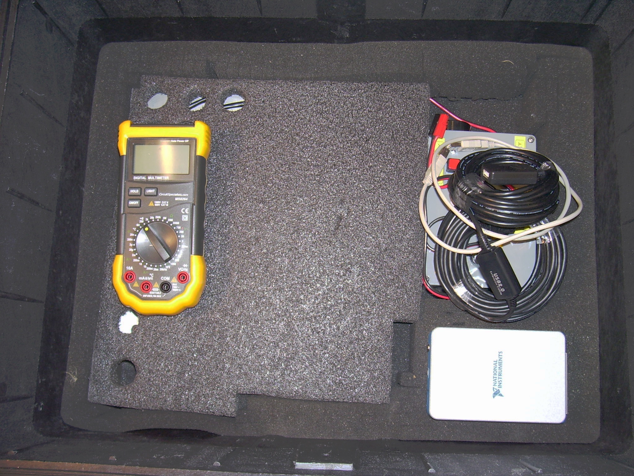
- Insert protective foam over test platform and load DMM, launch controller with key, 50-foot USB cable, short USB cable, and DAQ.
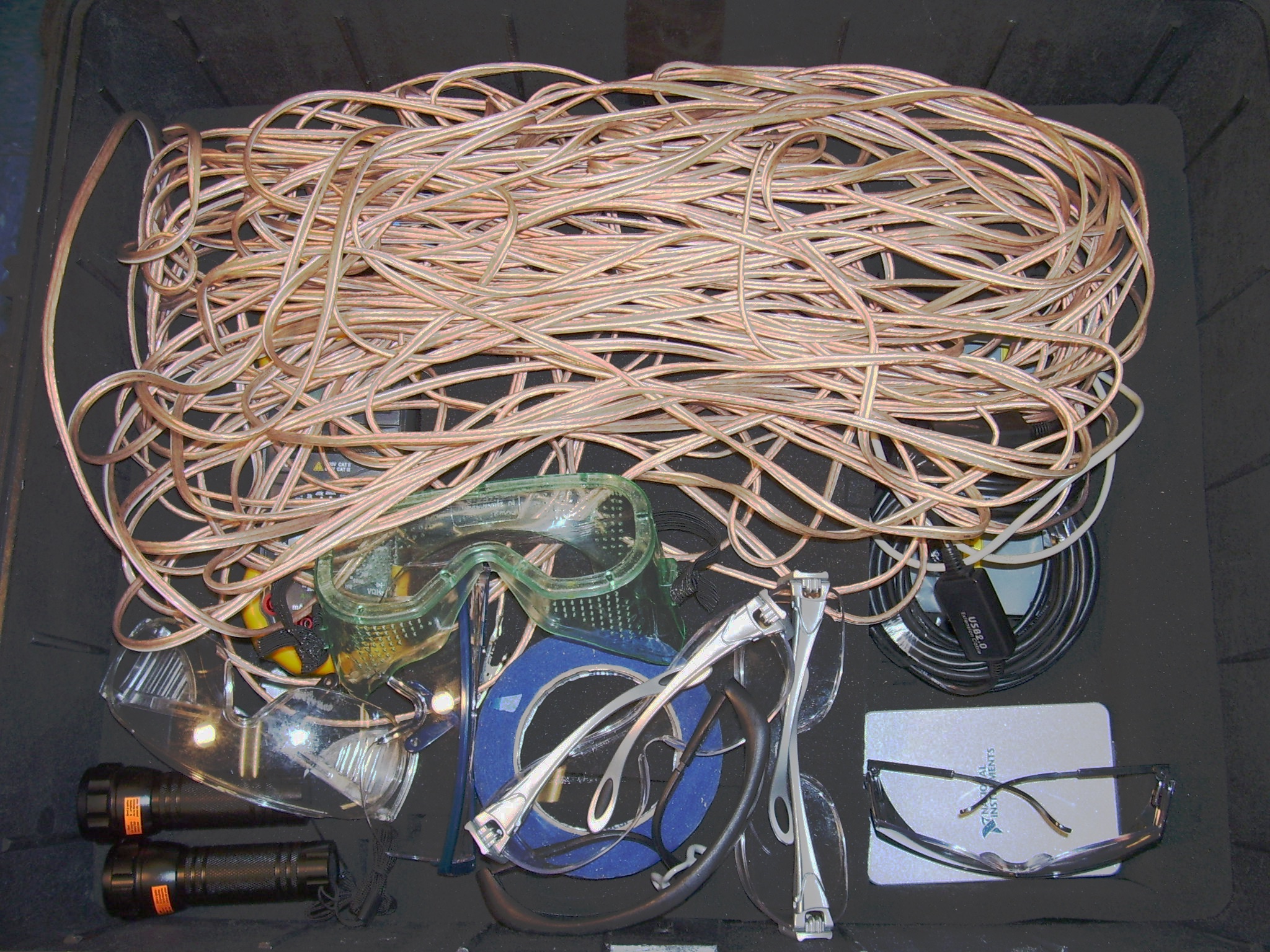
- Load tape, long launch control cable with alligator clips, safety goggles, and flashlights.
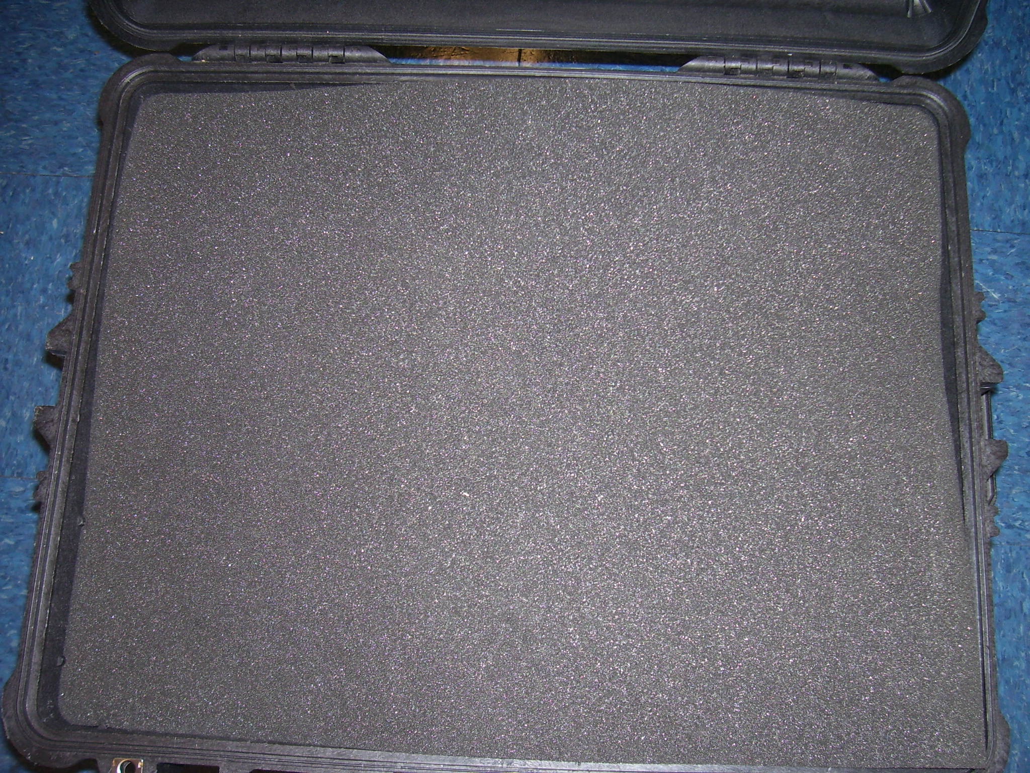
- Add protective foam and close and lock lid.
