The Final Project
Objective
By the end of the laboratory the student will:
- Create an experimental plan with scientific and/or engineering objectives.
- Design, prototype, test, and build an instrument package to achieve the objectives.
- Fly the experiments, gather and analyze the data from each one.
- Revise the experimental and flight plan for succeeding launches based on lessons learned from each flight.
Before You Begin – Things you have to fit in
The following things are not explicitly sequenced in the lab sessions. Nevertheless, you have to accomplish them before you launch. Plan accordingly:
- Calibrate your sensors. Whether this step needs to be done before you breadboard, while on the breadboard, or after they've been soldered to the PC board depends on the sensor and how you plan on processing the data, but you will need to verify the operation of your sensors and if necessary determine calibration constants. The pressure sensor calibration is described at the bottom of this old page.
- Assemble your rocket. Your kit needs to be assembled at some point. Make absolutely certain that you follow all college regulations regarding ventilation and skin protection for adhesives and spray paint. Sign for your kit in the book by the kits. There is a set of step-by-step instructions for the Barracuda (also useful for the Arreaux) here. I even agree with many (but not all) of the instructions.
The new version of the Arreaux has different assembly instructions than the previous version. You should reference the following documents: Arreaux Assembly and Operation Instructions (Note that these instructions need to be modified. See both the next two documents and the list below); Arreaux Motor Retainer Upgrade Notice; Aerotech 29 mm Motor Retainer Instructions.
- You won't need the 24 mm motor adaptor and don't need to construct it. Most of the parts are no linger in the kit.
- You need to replace the motor tube in the kit with a longer one to accomodate the 29/180 (or longer) motor casings. You'll have to cut one from one of the 17¾"or 32" motor tubes. A length of at least 15" will work for the 29/180 or shorter motors. You will need a length of at least 16¼" for the H115DM-14A, the H182R-14A, the H135W-14A, and the H195NT-14A, and a length of at least 19¾" for the I205W-14A.
- You MUST reinforce your body and payload tubes with a wrap of fiberglass. The instructions for fiberglassing are found here. Fiberglassing should be done after cutting your payload section to the correct length (and extending your body tube if necessary), but BEFORE any other assembly steps. Fiberglassing a completed rocket is extremely difficult and you lose most of the strength benefits that come from fiberglassing the tubes before any other assembly.
- You need to attach the included motor retainer instead of the Motor Hook, Thrust Ring, and Thrust Ring Flange. These changes are detailed in the Arreaux Motor Retainer Upgrade Notice. Attaching the motor retainer should be done after the rest of the rocket construction is completed (after Step 1 of the FINAL ASSEMBLY AND FINISHING in the instructions), otherewise it will block the application of the cyannoacrylate to the fin roots and the aft Centering Ring. Use JB Weld to attach it. The details are in the Aerotech 29 mm Motor Retainer Instructions.
- Use tapped holes and threaded #6 nylon screws to secure the nosecone to the payload section. Two is the minimum, three is recommended, four is allowed. Friction fitting with tape isn't sufficient.
- The Arreaux payload section is too short to fit the data logger and PC board. You'll need to fix the issue. A payload-section tube that is 14¾" long will just fit one of the E80 Prototype PC boards between the bulkhead and the nose cone. Feel free to examine the sample Arreaux and Tomahawk rockets for suggestions.
- It's often useful to be able to replace either the body or the payload/nosecone. The recessed screw eye on the payload section makes it difficult. You may want to make an extension out of 1/8" rope and a quik-link and attache the shock cord to the quik-link.
- Mount your PC board. Your completed PC board (see Section 3 below) needs to be secured in the rocket along with the battery. Paul Stovall has prepared a PDF of one method to mount the PC board and battery in the payload section. Consider it as a starting point for what you want to do. The instructions are here.
- Modify your rocket. Your instrumentation package will probably require some modification to the payload section or the nose cone. You need to design and make the modifications and verify they are structurally sound and function as intended. Walter Cook wants you to include some cushioning or shock absorpancy to protect the data loggers. We have a few extra nose cones and payload sections to allow for mistakes.
- Paint your rocket. Your rocket will function if not painted, but painting lends a finished and professional look.
- Learn how your data logger works and work out the data flow from sensor to data logger to computer to final report.
Budget: We have a list of parts and sensors that were purchased for the E80 labs and for your use. The inexpensive parts on the list or parts in the E80 lab or Engineering Stockroom you may use without regard to budget. However, if they run out, let us know. The expensive parts on the list or in the E80 lab are available in only limited quantities without special permission from your Lab Prof. These include all pressure sensors, instrumentation amplifiers, and OPA551's. Ask if you're not sure. Your team has a $50 budget for parts and sensors that are not on the list or in the stockroom. The budget is intended for parts, sensors, and construction supplies. It is not intended for motors. We have a list of potential sensors to get you started. We prefer that you order the parts using the standard Engineering Department order form. You'll want to get your parts ordered early so you can have them by your second design lab session. However, you can't order the parts until your experimental plan is approved by your section Prof. and Prof. Spjut.
On the form,
- NEVER hit the return key until you're completely finished with the form. Regardless of what field you're in, the return or enter key will submit it. You've been forewarned.
- Select Department under Please select one.
- For the Course/Class Put E80 and your Section and Team number, e.g., E80 Section 2 Team 5.
- Put the ordering person's name in the Requested By fields.
- IMPORTANT: Choose Clark, Christopher as the Faculty Advisor.
- Items Purchased Goes to client (that's you).
We order enough from from DigiKey or Mouser that you do not have to include shipping from either of them in your budget. If you order parts from other vendors, the shipping costs will be charged to your budget. Teams can pool orders to share shipping costs.
For some items such as spray paint, it's quicker and easier to pick it up yourself and turn in a reimbursement sheet. The reimbursement sheets need to be turned in by the day of your final presentation. Please order most things through the Department and keep reimbursement forms to a minimum.
Lottery: There will be a lottery or draft for selecting the remaining motors on Tuesday, 8 MAR 2016 at 9:35 AM. Each team will select four motors: two for the first launch day, and two for the second. The team order will be chosen by the luck of the draw. Rounds 3 and 4 will go in reverse order from rounds 1 and 2. For each of the four rounds each team will get one selection in turn. The motors from which you can choose are listed in a table below, so you can come prepared to select the motors you want for your flight. Rocksim or OpenRocket may help you prepare.
Data Logger: Your team gets one data logger to use for the duration of the final project. Sign for your data logger in the same book as for your rocket kit. We want it back at the end. If you manage to fry it or destroy it, your team gets to put in $25 apiece towards the replacement cost. The loggers have sixteen channels of sixteen-bit resolution, and a maximum composite sample rate of about 400 kSPS. If you use all sixteen channels at the maximum rate, you have a sample rate of 25 kSPS and a Nyquist frequency of 12.5 kHz for each channel. There are two slightly different versions of the logger: the MuddLog16 v3 from December 2012, and the MuddLog16 v4 from March 2015. They differ in the type and placement of the microSD holder and the as-manufactured pin height. The user manual for both is here. The layout of the MuddLog16 v3 is here. The schematic of the MuddLog16 v3 is here. The layout of the MuddLog16 v4 is here. The schematic of the MuddLog16 v4 is here.
You have to format your microSD as a FAT32 disk with 4k or 8k block sizes, which is fairly straightforward with Windows. It can be done on a Mac in the terminal window using the diskutil command. If you aren't a unix guru, don't try it on a mac. Do not edit the configuration file on a Mac unless you use BBEdit or TextWrangler. Other programs will make the configuration file unreadable for the data logger. We have two VIs and two MATLAB .m files for reading the data files. The first VI, ReadBinaryFileMuddLog16.vi, asks for the .dat or .DAT file, and then reads the file and plots the data in a window. The second VI, ReadPortionBinaryFileMuddLog16.vi, asks for the .dat or .DAT file, and then reads the portion of the file indicated by the start and stop times and plots the data in a window. It is most useful for reading a portion of a file that is too big to fit into memory all at once, or for reading just the flight portion of a data file. The first .m file contains a function, ReadBinaryFileTX, that generates 2D arrays of the sample times and the sample values in that order. The second .m file contains a function, ReadBinaryFileXT, that generates 2D arrays of the sample values and the sample times in that order (the opposite of the first function.
Video Camera: We have a #11 Keychain Camera available for each team to use during launch. They record 720P video to microSD cards. We want it back at the end. You will want to consider carefully how you want to mount one on your rocket if you want to use one. Since they don't use telemetry, you have to recover the microSD card to see the video. The manual (such as it is) is here. We have style number 2. We have flight videos from thses cameras here, here, and here.
Section 1 – An Experimental Plan – Due at end of first lab
By the end of the first Final Project lab session, you need to have your section professor and Professor Spjut approve your complete schematics (including the 0.1 µF capacitors on the power supply lines) and list of parts for your flight experiments. The steps to get you there are:
- Determine your science and/or engineering goals. What do you want to measure and why? Will you measure atmospheric phenomena such as temperature, pressure, humidity, trace gas concentration, particulate count, or wind speed? Will you measure rocket performance data such as altitude, velocity, acceleration, vibration, rotation rate, internal temperatures, or in-flight events, such as parachute ejection and landing? Are there novel things you want to try such as using an optical sensor to measure rotation rate?
- Determine what sensors or means you will use to achieve your science and/or engineering goals. You need to use at least two different types of sensors, one of which is recommended to have at least a 1 kHz bandwidth, and you have a maximum of sixteen channels of data that you can measure. A stand-alone altimeter or video camera doesn't count towards your minimum of two, but does count against your maximum count of sixteen.
- Determine if the response time of your sensors and the limitations of your data logger will permit you to make the measurements you want. You may need to use Rocksim or OpenRocket, atmospheric models, and 1st-order response models to determine transients. This link is a VI to process a data set through a 1st-order model. The test data file for it is here. To see to what degree you can recover your original signal, you can play with the first-oder deconvolution VI here.
- Determine what circuitry you will need to power the sensors and condition the outputs so that they will interface with the data logger. Analog Devices has a handy application note on single-sided power for op-amps.
- Generate a complete parts list and complete schematics (e.g., power and bypass capacitors for op-amps) for your sensors and signal conditioning.
- Discuss what you will need to process the data.
- Have your section professor and Professor Spjut approve the documentation of your plans.
- If there are any non-standard parts that you will need, we prefer that you order the parts using the standard Engineering Department order form. You'll want to get your parts ordered early so you can have them by your second design lab session. See details under Budget above.
Section 2 – Breadboard and Test– Due at end of second lab
Before you commit your design to final flight hardware, you need to make sure your design works. Fit all of your desired components except for the battery, the data logger, and any power regulators, on a single breadboard. Use proper breadboard technique where you trim resistors, capacitors, and other components to get them close to the breadboard, keep the interconnecting leads short, and use the power busses for power. Measure the current draw (with a multimeter) of your completed circuit and calculate the mAh required for your circuit to operate for one hour, and size your battery or batteries accordingly. Test your data logging on a USB DAQ and computer before you test it on the data logger to make sure the signals are in the 0-to-3.3V range. You can place the data logger, battery, and voltage regulators on a second breadboard. The data logger is too big for both sides to fit on a breadboard. Connect it so that the 20-pin side is on the breadboard, and the 5-pin side is hanging off.
Make sure everything works. Demonstrate that it functions to your section professor and Professor Spjut. You need to get approval on your functioning design by the end of the second Final Project lab session. If you have parts that haven't arrived, you'll have to get permission of your section instructor to delay the demonstration of functionality to the third session.
Section 3 – Mounted Flight Package- Due at end of third lab
Once your breadboarded design functions and is approved by your section professor transfer everything over to your flight PC board and solder it into place. Sign for your PC board in the same book as for the data logger and the rocket kit. The top of the PC board is identical to your breadboard with two exceptions: The four outside power busses are slightly nearer the five-pin rows on the breadboard, and there is an extra power bus that runs up the center of the board, that you can use or not use as you see fit. There is a section in the middle of the PC board designed to accept a 7805 +5V voltage regulator, and up to three other voltage regulators. The bottom of the board has mounting sockets for the data logger. Do not solder the data logger to the PC board. Simply put it in the sockets. The mounting holes on the PC board will accept either 4-40 or M3 screws. We have a fairly large collection of both 4-40 and M3 machine screws, nuts, and spacers available.
All of your circuitry has to fit on one PC board, with the exception of remote sensors, which must have leads going to the PC board. Once your circuitry has been transferred and soldered, test everything to make sure it still works. Once you have fixed any errors, demonstrate that your system functions to your section professor and Professor Spjut.
Section 4 – Flight Ready- Due at end of fourth lab
Even once your PC-boarded sensor and data logger package is working, you still need to get it on your rocket and make sure everything is ready. In addition, you need to actually perform a complete run-through of the launch checklist. You will load an empty motor casing instead of a loaded motor. Otherwise, you will complete the checklist. Launch pads will be available in the lab. A copy of the Aerotech Flight Card is found here. You may want to write and test any VIs or software processing routines you will need, so that you will be able to quickly check your flight data.
You also need to have a list of flight objectives for each flight and have it reviewed by your section professor or Professor Spjut.
To repeat: You want to be completely ready for pre-flight, flight, and data processing, and you want to have a complete run through of everything you will do in the field. It is much easier to debug and correct faulty procedures in the lab than on the high desert.
If your motors are not already pre-assembled, we'll want you to assemble and label your two motors for a given week in the lab session preceeding the flight day. For the reloadable motors, the motor assembly instructions are found here.
Important: You need to check the flight characteristics of your finished rocket in Rocksim or OpenRocket with the motors you will fly. The "M" delay is approximately 10 seconds. The "L" delay is approximately 14 seconds. If you need a delay longer than 10 seconds, check to see if we have an "L" delay available for your specific motor. Either the "M" or the "L" delay can be modified to burn shorter than the standard time. Again, RockSim or OpenRocket are excellent tools for helping you decide if you want to shorten the delay so that the 'chute pops out at apogee and not back on the ground. It's easiest to modify the delay time before you assemble the motor. We have two Aerotech RMS Delay Drilling Tools for adjusting the delays.
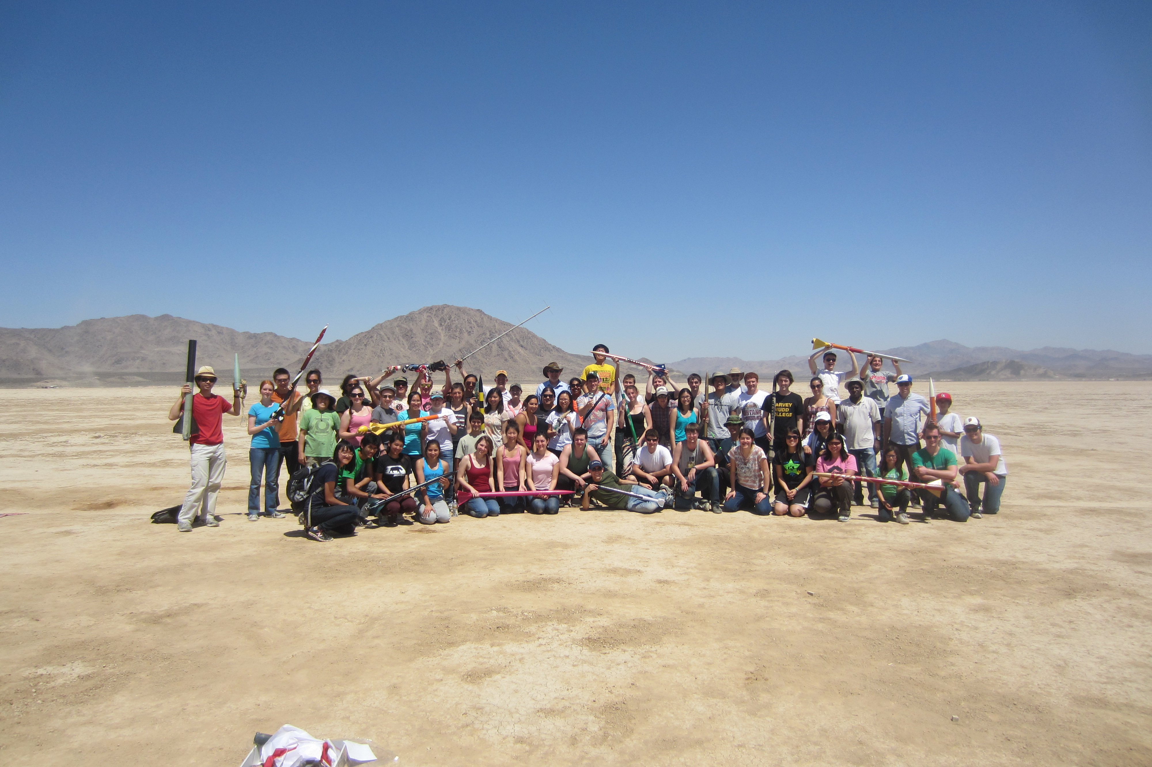
Section 5 – Launch
The buses to the Lucerne Valley launch site will leave from Foothill Blvd. in front of Parsons at exactly 6 AM on both 16 APR 2016 and 23 APR 2016. You should be there at least 15 minutes early. Anyone missing the bus will be responsible for getting themselves to the launch site. The GPS coordinates are N34° 29' 48.7" W116° 57' 30.2" which can be entered directly into Google Maps. We will have a simple breakfast, lunch, and water available. We will bring the E80 laptops and all of the loaded motors with us. We will also have sunscreen. Anything else you think you will need, you should bring with you. We will not pick up your rockets for you, you need to carry them. You are welcome to bring your own laptops. The desert mornings start off quite cool but the temperature may be hot before we leave. Dress accordingly. There is limited shade and no seating beyond what you bring for yourself.
At the launch site, assist with any final set up of the facilities, and then start prepping your rocket. The goal is to have the turnaround time be 1 hour per flight, but safety and accuracy trump speed. Please observe the safety barriers, pay attention to the Public Address system, and obey any directions from the Range Safety Officer (RSO) or the Launch Control Officer (LCO). The launch will be conducted according to the Tripoli High Power Rocket Safety Code (the NAR code is here for those who haven't memorized NFPA 1127).
For each of your flights you will need to complete a launch checklist and fill out a Flight Card and get it initialed by the Range Safety Officer (RSO), who will inspect your rocket and verify that your checklist is complete. You can then present the card and the rocket to the Launch Control Officer (LCO) to be assigned a launch pad. A copy of the Flight Card is found here.
You will want to assign one team member as a spotter who is assigned to stand some distance from the launch pad (at least 1000 feet for flights with apogees over 1000 feet, and at least the apogee distance for flight under 1000 feet) whose only responsibility is to follow the rocket during flight and recover the rocket after flight. The inclinometers from the First Flight lab will be available if you want to use them. There is one handheld GPS unit that can be shared among all of the teams to record locations as desired. We have occassionally brought additional GPS units from the Chemistry Department.
Section 6 – Recovery and Analysis
As mentioned on the checklist, you should record the location where the rocket landed if the GPS (or your own GPS) is available. You should inspect the rocket for damage. After you download the data in all of the forms required on the checklist and have reported any damage to the RSO, start prepping for your second flight.
It would be wise to use the time before your next flight to examine your data and do some preliminary analysis on them to see if you have met your objectives for the flight. You can be as thorough in your analysis as time and your computing power allows. You may want to modify your flight plan according to the data that you have analyzed.
If a major hardware failure keeps you from getting data from one or more flights, you need to let us know.
Section 7 – Repair and Re-fly
The week in between launches is for you to figure out what went wrong, fix it, and prepare for your next round. If everything went right and you're already all set for your second week, enjoy it. It will be the last time in your life. For us normal mortals, something didn't behave as we expected, or we learned something that made us ask a new question. Take the time to think about what you have accomplished, what you want to accomplish, and how best to bring it to pass.
We'll want you to assemble and label your two motors for a given week in the lab session preceeding the flight day.
Important: You need to check the flight characteristics of your finished rocket in Rocksim or OpenRocket with the motors you will fly. The "M" delay is approximately 10 seconds. The "L" delay is approximately 14 seconds. If you need a delay longer than 10 seconds, check to see if we have an "L" delay available for your specific motor. Either the "M" or the "L" delay can be modified to burn shorter than the standard time. Again, RockSim or OpenRocket are excellent tools for helping you decide if you want to shorten the delay so that the 'chute pops out at apogee and not back on the ground. It's easiest to modify the delay time before you assemble the motor. We have two Aerotech RMS Delay Drilling Tools for adjusting the delays.
Section 8 – Write Up
The sixth week of the project is for writing your Final Report and preparing your Final Presentation.
Other Information
We will have three rows of launch stands at Lucerne Valley. The front row is for motors with an impulse of G or lower. There will be three 1/4" launch rods and one chagable between 1/8" and 3/16". The middle row will have two 1/4" launch rods on a single stand and four stands that will be set up with 1/4" launch rods, but can be switched to 1/4" launch rails. The back row will consist of a single 1/4" launch rail (but can be switched to a 1/4" launch rod) for K and larger impulse motors or for complex rockets (such as two-stage rockets).
As long as you stay within your $50 budget, you are not limited to the rocket kits from class. If you have a justifiable science or engineering objective you can buy, make, and fly any other rocket you would like, up to your level of certification. If you want to fly your Quest Seeker again (with or without the altimeter) you can do so. In addition, if you want to buy, build, and fly a rocket just for fun, you are welcome to do so. The restrictions are:
For Project Related Rockets:
- You must stay within your $50 budget.
- You must justify the reason for the flight and have it approved.
- You need to let us know what motors you need before the end of March.
- You my fly rockets up to your level of certification. If you are not certified, the rocket must fly on G or smaller motors.
- They will require General Flight Cards and will be inspected by the RSO and LCO.
For Personal Rockets:
- It can't interfere with your team's project flights.
- You my fly rockets up to your level of certification. If you are not certified, the rocket must fly on G or smaller motors.
- If you need a launch rod other than 1/8", 3/16", or 1/4" diameter, you must inform us before the end of March.
- We have a large supply of surplus motors with impulses ranging from A through I. If your rocket can use one of these, you may use it free of charge. Ask Prof. Spjut for the complete list. If you are not using one of our surplus motors you are responsible for purchasing the motors and igniters.
- They will require General Flight Cards and will be inspected by the RSO and LCO.
Lucerne Valley Temperature Data
Reference temperature data from flights at the Lucerne Valley Dry Lake Bed are available at the bottom of the Temperature Lab page.
Existing Parts (not updated for 2016 )
| Supply on 25 MAR 2013 |
Part Number |
Name/Description |
Manufacturer |
Supply Voltage |
Output Range |
Some Uses |
| 201 |
TL081 |
IC OPAMP |
|
±4V to ±18V |
±3V to ± 16V |
General Purpose op-amp, buffer, gain, transimpedance, filter |
| 146 |
OP-07 |
IC OPAMP |
|
±3V to ±22V |
±1V to ±12.6V |
General Purpose op-amp, buffer, gain, transimpedance, filter |
| 46 |
OPA551PA |
IC OPAMP GP 3MHZ SGL HV 8DIP |
Texas Instruments |
±4V to ±30V |
±2V to ± 28V |
High-current output op-amp, buffer, gain, filter, drive high-current load |
| 5 |
MCP6002-I/P |
IC OPAMP 1.8V 1MHZ DUAL 8-DIP |
Microchip Technology |
1.8V to 6V SS |
1.8V to 6V |
Battery-powered op-amp, buffer, gain, transimpedance, filter |
| 151 |
MCP6004-I/P |
IC OPAMP QUAD 1.8V 14DIP |
Microchip Technology |
1.8V to 6V SS |
1.8V to 6V |
Battery-powered op-amp, buffer, gain, transimpedance, filter |
| 124 |
MCP601-I/P |
IC OPAMP SNGL SUPPLY R-R 8DIP |
Microchip Technology |
2.7V to 6V SS |
2.7V to 6V |
Battery-powered op-amp, buffer, gain, transimpedance, filter |
| 48 |
AD623ANZ |
IC AMP INST R-R LP 8DIP |
Analog Devices |
3V to 12V SS |
3V to 12V |
Battery-powered Instrumentation Amp, pure gain, 1 ≤ G ≤ 1000 |
| 76 |
7805 |
Voltage Regulator |
|
7V to 35V |
5V |
Voltage regulator, supply power at 5V, up to 1A |
| 60 |
MCP1702-3302E/TO |
IC REG LDO 3.3V 250MA TO-92-3 |
Microchip Technology |
4V to 13.2V |
3.3V |
Voltage regulator, supply power or virtual ground at 3.3V |
| 104 |
MCP1702-3002E/TO |
IC REG LDO 3V 250MA TO-92-3 |
Microchip Technology |
3.7V to 13.2V |
3V |
Voltage regulator, supply power or virtual ground at 3V |
| 208 |
MCP1702-2502E/TO |
IC REG LDO 2.5V 250MA TO-92-3 |
Microchip Technology |
3.2V to 13.2V |
2.5V |
Voltage regulator, supply power or virtual ground at 2.5V |
| 173 |
MCP1702-1802E/TO |
IC REG LDO 1.8V 250MA TO-92-3 |
Microchip Technology |
2.7V to 13.2V |
1.8V |
Voltage regulator, supply power or virtual ground at 1.8V |
| 68 |
MCP1702-1502E/TO |
IC REG LDO 1.5V 250MA TO-92-3 |
Microchip Technology |
2.7V to 13.2V |
1.5V |
Voltage regulator, supply power or virtual ground at 1.5V |
| 10 |
SEN-09412 |
Gyro Breakout Board - LPR5150AL Dual 1500°/s |
Sparkfun |
2.7V to 3.6V |
0 to 3V |
IMU, rate gyro (x & y axes) |
| 10 |
SEN-09425 |
Gyro Breakout Board - LPY5150AL Dual 1500°/s |
Sparkfun |
2.7V to 3.6V |
0 to 3V |
IMU, rate gyro (x & z axes) |
| 10 |
SEN-09652 |
Triple Axis Accelerometer Breakout - MMA7361 |
Sparkfun |
2.2V to 3.6V |
0 to 3V |
IMU, 3-axis accelerometer, ±1.6g, ±6g |
| 10 |
876-1002-ND |
ADXL335Z EVAL BOARD |
Digikey |
1.8V to 3.6V |
0 to 3V |
IMU, 3-axis accelerometer, ±3g |
| 10 |
MMA2201EG |
SENSOR ACCEL X-AXIS+/-40G 16SOIC |
Freescale |
5V |
0 to 5V |
IMU, High-g acceleration measurements |
| 200 ft. |
TT-E-40-200 |
40 AWG Type E thermocouple wire |
Omega Engineering |
N/A |
6.998 mV @ 100°C |
Temperature measurement, fast response time |
| 200 ft. |
FF-E-24-200 |
24 AWG Type E thermocouple wire |
Omega Engineering |
N/A |
6.998 mV @ 100°C |
Temperature measurement, moderate response time |
| 250 |
NTCLE100E3104JB0 |
THERMISTOR NTC 100K OHM LEADED |
Vishay |
N/A |
100kΩ @ 25°C |
Cold Junction Compensation, Temperature Measurement |
| 25 |
MCP9701A-E/TO |
IC SENSOR THERMAL 3.1V TO-92-3 |
Microchip Technology |
3.1V to 5.5V |
400mV + 19.5mV/°C |
Cold Junction Compensation, Temperature Measurement |
| 44 |
MPX53DP |
SENSOR DIFF PRESS 7.25PSI MAX |
Freescale |
3V to 6V |
0 to 60mV |
Pitot Static tube, Differential Pressure Measurement |
| 47 |
MPXA6115AC7U |
DIP Absolute Pressure Sensor 16.7 PSI |
Freescale |
5V |
0 to 4.75V |
Altimeter, Barometer |
| 62 |
BPW46 |
PHOTODIODE PIN FLAT SIDE VIEW |
Vishay |
N/A |
See Data Sheet |
Light Intensity Measurement, irradiance, light scatter |
| 57 |
OP950 |
PHOTODIODE PIN 935NM SIDELOOK |
TT Electronics/Optek Technology |
N/A |
See Data Sheet |
Light Intensity Measurement, irradiance, light scatter |
| 205 |
|
Red LED |
|
20 mA |
Unknown |
Light source, light scattering measurements |
| 125 |
|
Green LED |
|
20 mA |
Unknown |
Light source, light scattering measurements |
| 250 |
|
Yellow LED |
|
20 mA |
Unknown |
Light source, light scattering measurements |
| 360 |
SR205E104MAR |
CAP CER .10UF 50V 20% RADIAL |
AVX Corp. |
50V max |
N/A |
Power Supply Bypass |
| 50 |
123-4016-GR |
9V T Battery Snap |
Mouser |
9V |
9V |
Connect 9V battery |
| 20 |
WIG-10216 |
Logomatic 8 Channel Data Logger |
Sparkfun |
3.6V to 7.5V |
3.3V |
8 channel data logger. 10-bit ADC. Measurement range 0 – 3.3V |
| 2 |
WIG-09228 |
uLog 3 Channel Data Logger |
Sparkfun |
3.3 V |
N/A |
3 channel data logger. 10-bit ADC. Measurement range 0 – 3.3V |
| 9 |
LM555CNFS |
IC OSC MONO TIMING 8-DIP |
Fairchild |
4.5V to 16V |
VS – 2V |
Timer, Pulse Train Generator, Pulse Generator |
| 25 |
ICM7555IPAZ |
IC OSC MONO TIMING 1MHZ 8DIP |
Intersil |
2V to 18V |
VS – 1V |
Improved 555-style Timer, Pulse Train Generator, Pulse Generator |
| 3 |
XR2209CP-F |
IC FUNCTION GENERATOR 8PDIP |
Exar |
8V to 26V |
Varies |
Square Wave or Triangle Wave Generator |
| 30 |
|
10 Position .1" Female Headers |
|
|
|
Socketing for IMU2 or IMU3, requres 2 |
| 2 |
HCH-1000-001 |
Capacitive Humidity Sensor |
|
|
|
|
| 7 |
Various |
Assorted Gas Sensors |
|
|
|
|
| 5 |
|
Gas Sensor Sockets |
|
|
|
|
| 3 |
|
Sharp Dust Sensor |
|
|
|
|
| 6 |
|
Vibration Sensor |
Measurement Specialties Inc. |
|
|
|
| 23 |
|
Vibration Sensor/Dynamic Strain Gauge |
Measurement Specialties Inc. |
|
|
|
| 81 |
|
Vibration Sensor/Dynamic Strain Gauge w/adhesive |
Measurement Specialties Inc. |
N/A |
up to 20V+ |
|
A Partial List of Potential Sensors (not updated for 2016 )
The sensors listed below are potential sensors to use on your final project. The list is not exhaustive. Additional places to look are Digikey, Mouser, Sparkfun, Component Distributors, and others. Component Distributors takes about 10 days to deliver, but they have some good gas sensors.
The Assigned Motors
16-APR-2016 |
|
23-APR-2016 |
| Sec 1 Team 1 |
G79W-M, G79W-M |
|
Sec 1 Team 1 |
I205W-14A**, G79W-M |
| Sec 1 Team 2 |
I205W-14A**, H115DM-14A* |
|
Sec 1 Team 2 |
G80NT-14A, G80NT-14A |
| Sec 1 Team 3 |
H135W-14A*, G125T-14A |
|
Sec 1 Team 3 |
G79W-M, G79W-M |
| Sec 1 Team 4 |
G75J-M, G125T-14A |
|
Sec 1 Team 4 |
H195NT-14A*, G125T-14A |
| Sec 1 Team 5 |
G80NT-14A, G125T-14A |
|
Sec 1 Team 5 |
H135W-14A*, G80NT-14A |
| Sec 2 Team 1 |
H238T-M, G79W-M |
|
Sec 2 Team 1 |
H165R-M, G79W-M |
| Sec 2 Team 2 |
H165R-M, G79W-M |
|
Sec 2 Team 2 |
H128W-M, G79W-M |
| Sec 2 Team 3 |
H182R-14A*, G79W-M |
|
Sec 2 Team 3 |
I205W-14A**, H115DM-14A* |
| Sec 2 Team 4 |
H238T-M, G79W-M |
|
Sec 2 Team 4 |
H238T-M, G125T-14A |
| Sec 3 Team 1 |
H195NT-14A*, G80NT-14A |
|
Sec 3 Team 1 |
H182R-14A*, G125T-14A |
| Sec 3 Team 2 |
I205W-14A**, G79W-M |
|
Sec 3 Team 2 |
G79W-M, G77R-M |
| Sec 3 Team 3 |
H128W-M, G77R-M |
|
Sec 3 Team 3 |
H238T-M, G79W-M |
| Sec 3 Team 4 |
H195NT-14A*, G75J-M |
|
Sec 3 Team 4 |
H182R-14A*, G75J-M |
| Sec 3 Team 5 |
H135W-14A*, G80NT-14A |
|
Sec 3 Team 5 |
H135W-14A*, G125T-14A |
| Sec 4 Team 1 |
H182R-14A*, G75J-M |
|
Sec 4 Team 1 |
H115DM-14A*, G80NT-14A |
| Sec 4 Team 2 |
H115DM-14A*, G80NT-14A |
|
Sec 4 Team 2 |
H195NT-14A*, G75J-M |
| Sec 4 Team 3 |
H165R-M, G79W-M |
|
Sec 4 Team 3 |
H165R-M, G79W-M |
| Sec 4 Team 4 |
H128W-M, G80NT-14A |
|
Sec 4 Team 4 |
H238T-M, G80NT-14A |
| Sec 4 Team 5 |
H238T-M, G125T-14A |
|
Sec 4 Team 5 |
H128W-M, G75J-M |
The Motors Available for Launch
| Motor |
Casing |
Total Impulse |
16-APR-16 |
23-APR-16 |
| For Aerotech Rockets |
| G77R-M |
29/120 |
105 |
2 |
2 |
| G79W-M |
29/120 |
109 |
8 |
8 |
| G125T-14A |
29 SU |
128 |
5 |
5 |
| G80NT-14A |
29 SU |
132 |
5 |
5 |
| G75J-M |
29/180 |
136 |
3 |
3 |
| H165R-M |
29/180 |
165 |
2 |
2 |
| H238T-M |
29/180 |
166 |
3 |
3 |
| H115DM-14A* |
29 SU |
172 |
2 |
2 |
| H128W-M |
29/180 |
173 |
2 |
2 |
| H182R-14A* |
29 SU |
218 |
2 |
2 |
| H135W-14A* |
29 SU |
226 |
2 |
2 |
| H195NT-14A* |
29 SU |
236 |
2 |
2 |
| I205W-14A** |
29 SU |
345 |
2 |
2 |
*Rockets flying with these motors require an extra-long motor mount.
**Rockets flying with these motors require an extra-extra-long motor mount and an extra-long body tube.
A lottery will be held for the motors on Tuesday, 8 MAR 2016 at 9:35 AM.
PML Information
We have a very limited number of PML kits and a number of pre-assembled PML rockets available. Talk with your section professor if you feel you need a PML kit.
There is a set of step-by-step instructions for the X-Calibur (even though it says Phobos) here.
There are modifications to the included plans. For the Phobos or X-Calibur they include:
- You need to attach the HAMR motor retainer which requires that the motor tube protrudes 3/8" from the end of the rocket, instead of being flush. The detailed instructions are found here.
- You need to install the linear launch rail lugs instead of the 1/4" launch lugs in the instructions.
- Make sure that the fins project perfectly straight from the rocket. Even a degree or two of misalignment will cause your rocket to spin or veer off course. Take your time and get it right.
- Make sure your ejection piston slides freely. Sand it until it does.