Accelerometer and Gyroscope Calibration
Objective
By the end of the laboratory the student will:
- Use the principles of Propagation of Errors to develop and implement a method to calibrate MEMS accelerometers.
- Use the principles of Propagation of Errors to develop and implement a method to calibrate MEMS rate gyroscopes.
- Develop a method for analyzing the dynamic data from MEMS accelerometers and rate gyroscopes. Use the developed calibration data and analysis method to compare the results from the accelerometers and rate gyroscopes with a known motion.
Preliminary Notes
Detailed procedures for running these experiments will not be given to you.
You are expected to develop the procedures and explain why you chose them. However, it is acceptable (and recommended) to consult with the proctors and professors as you plan your experiments.
If you are uncertain, ask. If the proctor or professor is uncertain, call my cell and ask me.
The overall goal of this lab is to calibrate accelerometers and rate gyroscopes so that you you could design, build, and calibrate an IMU as part of your final project, and then analyze the flight data and determine the acceleration, velocity, position, and orientation vectors of your rocket during its flight. Your write-up should include calibration expressions and uncertainties in the calibration constants. It should also have an explanation as to how you would process flight data.
If you have developed VIs for use, please include print-outs of the front panel and the block diagram in your write-up.
Equipment Protection and Safety
PLEASE follow these guidelines to protect yourself and the hardware on the Accel & Gyro (Turntable) Lab:
- The turntable has safety switches to stop it almost immediately when the protective lid is lifted. Never override the switches. You can stop the turntable quickly by lifting a corner part way.
- Always make certain that everything is secured on the turntable. Loose parts or parts that can become loose will fly off and potentially damage things. Be especially careful with batteries and such. Think about the direction of your acceleration vectors and arrange things so that at high g's things are forced together and not apart.
- The bracket for the breadboard is designed to securely hold the breadboard with the metal brackets and thumbscrews. Do not use tape to secure the breadboard. Ask a proctor or professor if you need help.
- Do not completely remove the breadboard bracket. You can loosen the screws to slide it into its alternate position, but do not remove the screws and shift it to another location on the table.
- Make sure the DAQ and the battery pack are secured in their respective brackets.
- Make sure that wires and cables are tied down and can't flop around to hit the protective lid. If a wire or cable comes free and starts to hit the lid (you'll hear a flap-flap-flap-flap-... sound) stop the turntable immediately.
- Blue masking tape is acceptable to secure wires and very small parts. Tape of any kind is NOT acceptable for securing batteries, breadboards, DAQs, or other large structural items.
- If you use duct (or duck) tape on ANYTHING in the lab I will force you to watch teletubbies reruns for 24 hours straight.
- If you use 9V batteries for your circuits, please put the 9V batteries back in the recharger at the end of a lab session (this rule goes for all labs).
- If you use a 7-DOF IMU, build and test your voltage regulator circuits BEFORE you connect power to the IMU. Power applied to the wrong pins will destroy it. Also check that the 3-axis accel is not asleep.
- Don't put anything, especially hands or fingers, under the turntable. There are lethal voltages and loose wires. In addition, there are moving parts that can cut you or get jammed.
- Don't shift the position of the turntable on the large table. The turntable and frame must be screwed together and supported in multiple places before shifting. Also the wires can get tangled or pinched if not moved properly.
Section 1 – Turntable Calibration
Note: The detailed instructions for use of the turntable may have changed by the time you get to lab. Always check with a proctor or professor for the latest instructions.
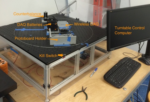
Connect the laptop to the data acquisition system (if not already connected). Start the laptop. Start LabVIEW 2011, and load the ControlTurntableLV11.vi, but do not start it. Plug in the turntable. The turntable will not operate unless the lid is down. Always counterbalance any loads on the turntable with an equivalent load on the opposite side of the table.
The counterbalancing doesn't have to be perfect, but if the table wobbles at 150 RPM, you need to counterbalance things better.
Set the desired speed and direction in the ControlTurntableLV11.vi. Start the VI by either clicking on the RUN arrow or typing Ctrl-R. Stop the VI by clicking the stop button or by pushing the END key.
Use a stopwatch to verify the table rotation at 60 RPM, 120 RPM, and 180 RPM in both the clockwise and counterclockwise directions.
Section 2 – Accelerometer and Rate Gyroscope Calibration
The wireless DAQ is an NI WLS-9205 (listed as WLS-15819C2 in the Measurement and Automation Explorer). Attaching the wires or leads requires a small screwdriver and is counterintuitive. Ask a proctor or professor for help. There is not a pre-existing VI for reading from it. You are expected to make your own.
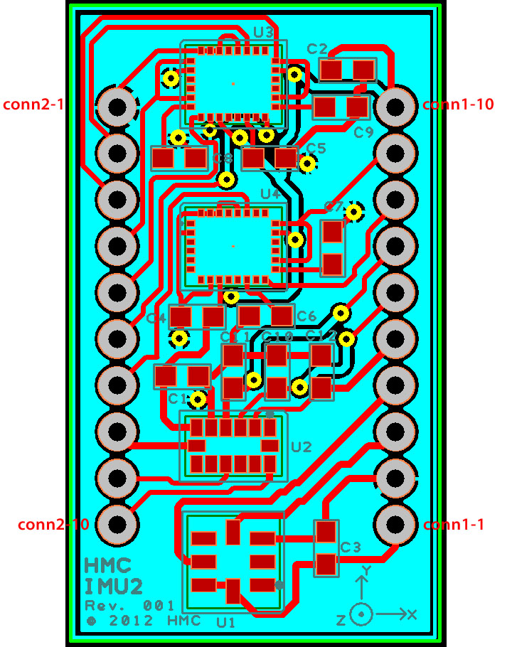
There have been four different IMUs produced for E80. IMU1 is no longer used. There is a limited number of IMU2s available. They were used for this lab in 2012 and 2013. They function well, but the rate gyro chips are out of production, which led to IMU3. There is a limited number of IMU3s available. They were used in the lab in 2014. They function well, but the accelerometer chips are out of production, and the rate gyros had too wide of a data span, which led to IMU4. IMU2, IMU3, and IMU4 are all 20-pin DIP boards and are physically very similar. They can be distinguished by the name IMU2, IMU3, or IMU4 on the front of the board. The pin-outs were kept as similar as possible among the three. However, there are significant differences. A list with a pin-out comparison is available here. The power requirements and the power and ground pins have not changed. The table below lists the important characteristics.
To power the accelerometers and rate gyros you need a stable voltage source. A battery is typically not stable enough. The most frequently used stable voltage source is called a linear voltage regulator. We have the following regulators in stock to provide 5V, 3.3V, 3V, 2.5V, and 1.5V. See the table below. The datasheets have typical application circuits. Check with a proctor or professor if you're unsure how to use a 9V battery and a voltage regulator to power your circuit.
The IMU has a small diagram indicating coordinate axes for the IMU. The pinouts for the chips use the names of the pins on the data sheets. The lectures on rocket dynamics have their own set of coordinate directions. DO NOT ASSUME THAT ANY OF THESE SETS OF COORDINATE AXES ARE THE SAME. You will want to determine how the chips are oriented on the IMU, how the pin labels correspond, how these correspond to the rocket dynamics coordinates, AND verify them experimentally. There is a simple way to verify the coordinate directions for the accelerometers using the gravity vector. It can also be used for a quick and easy calibration of the accelerometers.
If you choose not to use the 7-DOF IMU, there are two different 3-axis accelerometers available for calibration: the MMA7361 from Freescale and the ADXL335 from Analog Devices. They are both on break-out boards to give you easy access to the pins. The data sheet for the ADXL335 breakout board is here. The info for the other board is on the Sparkfun website. You need to supply power of between+2.2V and +3.6 V to the Vcc input for the MMA7361, and between +2.2 V and +3.6V for ADXL335. A 9V battery and a regulator or the +5V output on the DAQ can be useful. Don't forget to connect the ground. All of the sensors have lowpass filters with a bandwidth of about 50 Hz on the output. The MMA7361 can be switched to output either a range of ±1.5 g or ±6 g. The ADXL335has a fixed output range of ±3 g. Make sure you set the sleep switch correctly. If you are getting no output, you have set it incorrectly.
Also if you choose not to use the 7-DOF IMU, there are two different 2-axis rate gyroscopes available for calibration. They are the ST Microelectronics LPR5150AL and the ST Microelectronics LPY5150A . They have a range of ±1500°/s and require a voltage between 2.7V and 3.6V. The breakout board has lowpass filters on it and both 1X and 4X outputs. The 4X outputs have amplifiers with a gain of 4 on them so they can measure up to ±375°/s. The info for the boards are on the Sparkfun website.
It is up to you how you arrange and connect the sensors for testing and calibration. There is a fixture for holding your protoboard in different orientations
The DAQ uses WiFi to connect with your computer. You can connect it to your sensors as you see fit. For anything not dead center on the turntable, place a counterweight on the opposite side of the turntable to balance it. Be certain that everything is anchored securely before starting the turntable. Stop the motor immediately if anything is hitting the lid.
The manner you use the turntable for calibration is up to you, as long as you use it in a safe manner. Don't forget error analysis. Please explain your calibration strategy and protocol to a proctor or a professor before beginning calibration. Have the professor or proctor annotate your lab report to indicate this explanation has been completed. You will receive a zero (0) for Section 2 if the annotation is not in your lab report. Please make careful note of anything that doesn't work.
Section 3 –Calibration Use
As (possibly) explained in the lecture, the angular orientation of the accelerometer is required to integrate the accelerations to obtain 3-D velocities and positions. The rotation rates from the gyroscope must be integrated to obtain the angular orientation. You can wait until the final project to develop a full 6-DOF transformation and integration routine. However, it is worth doing a preliminary check. Set up your system to one axis of the rate gyro and the necessary axes of the accelerometer. For (at least) one trial, measure the starting angle of the turntable and the position of the accelerometer on it, start the data recording, rotate the turntable for a small number of revolutions (either by hand or with the control software), count the revolutions, and measure the final angle (and position). Then analyze the data and see how close your calculated final angle and position are to your actual final angle and position.

