Mudd I – Data Overview
Overview of Acceleration, Altitude, and Vibration Data
The complete time data of the flight are presented below. Click on the images to see the large versions. Then click the browser back arrow to return. The data are available in text files as both raw hexidecimal A/D values and interpreted acceleration, altitude, and voltage values for both the telemetry data sampled at 10 Hz, and the stored data sampled at 200 Hz. The files are Interpreted 200 Hz, Interpreted 10 Hz, Raw 200 Hz, Raw 10 Hz.
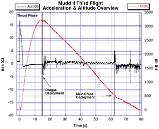
These are the overall acceleration and altitude data from the R-DAS. The R-DAS only has a 10-bit resolution. The quantization of the altitude data is clearly visible in the discrete steps in the red curve. The peak acceleration during the launch phase is around 6 g's. The ejection charge firing, the parachute opening, and the landing are clearly visible in the acceleration portion of the curve. The portion of the flight where the 'chute hadn't opened and the rocket was reaching a high terminal velocity is visible in the -1 g section of the acceleration curve.
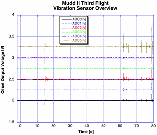
The vibration sensors have a steady-state output of 0 V, and can swing ±. They were DC-biased to give a steady-state output of approximately 2.6 V and show variations around that DC value. The op-amp used to condition the vibration sensors was an AD704, which is not a rail-to-rail op-amp. The system was powered from a 9 V supply, so the signal could go from about -0.5 V to over 5 V. The R-DAS can record voltages between 0 V and 5 V. The vibration sensors saturate the op-amp outputs both positive and negative at ejection, chute-opening, and touchdown.
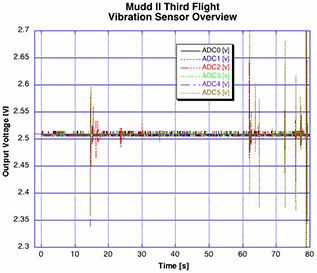
In this scale expansion of the vibration sensors, it can be seen that for most of the flight, the magnitude of the vibration-sensor signals is less than 100 mV. It will become clear in the time-expanded figures, that a great deal of that 100 mV on many of the channels is due to the R-DAS information beeper that can be clearly heard in the video. It's unclear at this time if the vibration sensors are picking up the vibrations in the rocket body caused by the beeper, or if the beeper draws so much current when it beeps, that the DC baseline of the R-DAS/conditioning board shifts. Our best guess is that the principal motion is the DC baseline shift and there is a little bit of pick-up of the aliased vibrations caused by the beeper. We welcome contrasting opinions. The conditioning gain in the next flight will be about 20X higher, so any actual vibration-sensor signal will be amplified by a factor of 20, and the baseline shift should not change in magnitude.


