Gen 1 IMU
The major electrical components used in the Gen 1 IMU are listed below. The schematics and PCB layouts were constructed in PCB Artist, a schematic capture and board layout package available for no cost from Advanced Circuits (if you would like the schematics or PCB layout in another form please contact Prof. Erik Spjut). The boards were fabricated by Advanced Circuits.There were four boards in total:
- The main board, Schematic, PCB layout
- The accelerometer daughter board, Schematic, PCB layout
- The rate gyro daughter board, Schematic, PCB layout
- The Pitot-static remote board, Schematic, PCB layout
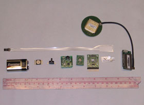
The accelerometers were arranged so that the ADXL78 measured acceleration along the axis of the rocket, and the ADXL320 measured the acceleration in two orthogonal radial directions. There were two IDG300s for angular rate measurements. They were arranged to provide redundant measurements along the axis of the rocket and single measurements along the same two orthogonal radial directions as the ADXL320. The main board also contained the altimeter pressure sensor (MPXAZ4115A) and the conditioning circuits for the thermistors (voltage divider followd by an op-amp buffer), the Pitot-static remote board, and the on-board sensors. The output levels were all in the 0 to 5 V range for interfacing with the R-DAS Tiny's 6 analog inputs.
| Part Description | Part Number | Manufacturer | Voltage Req | Current Req (mA) | Physical Input | Output Range | Bandwidth or Response Rate |
| High-g MEMS accelerometer | AD22279-A-R2 (ADXL78) | Analog Devices | 5 | 2 | Accel. ±35 g | 0.575 to 4.425 V | 400 Hz |
| Dual axis accelerometer | ADXL320 | Analog Devices | 3 to 5 | 1 | Accel. ±5 g | 0.6 to 2.4 V | 2500 Hz |
| Dual-axis rate gyro | IDG300 | InvenSense | 3.0 to 3.3 | 10 | Ang. Vel. ±500°/s | 0.5 to 2.5 V | 140 Hz |
| Pressure transducer | MPXAZ4115A | Freescale | 5 | 7 | Pressure 15 to 115 kPa | 0.2 to 4.8 V | 1 ms |
| Diff. pressure transducer | MPXV5050GP | Freescale | 5 | 7 | Pressure 0 to 50 kPa | 0.2 to 4.7 V | 1 ms |
| Thermistors | ATH10KR8 | Analog Technologies | Temperature | 10 kΩ nominal | <1 s | ||
| Thermistors | NTSD1XH103FPB50 | Murata | Temperature | 10 kΩ nominal | <10 s | ||
| Precision quad op-amp | AD8608 | Analog Devices | 5 | 1 | Voltage 0 to 5 | 0.02 to 4.98 V | 10 MHz |
| Precision 3 V reference | REF193 | Analog Devices | 4 to 15 | 0.045 | N/A | 3.00 V | N/A |
| Precision 5 V reference | REF195 | Analog Devices | 6 to 15 | 0.045 | N/A | 5.00 V | N/A |
The company contacted to populate the main boards and the rate gyro daughter boards did a poor job even after repeated resubmissions for repair. Our final yield was two fully-functioning IMUs and six IMUs with one or more sensors malfunctioning.