What Do We Want to Measure?
The principal reason for flying the rocket is to make and analyze measurements. Without the measurements, we're simply setting up the students to go "wow!" So what measurements can and should we make? An extensive literature and web search resulted in a large number of fairly light and low-cost sensors being available. The question was which ones to use. We divided up the sensors into three groups: navigation, ambient sensors, and vibration.
Beginning with vibration: The existing E80 instruments a freeway overpass with accelerometers and measures the response of the accelerometers to ambient noise and to a sledgehammer. We wanted to replicate the accelerometer-type data, but miniature accelerometers that have the bandwidth to measure modal vibrations are at least $100 apiece. A pair of accelerometers would have eaten up most of the sensor budget. Fortunately, Measurement Specialties Inc. manufactures a series of piezoelectric dynamic strain gauges that are quite inexpensive. If firmly attached to a component in the rocket, they will measure flexing or vibration of that component. While they don't measure acceleration, they do measure dynamic strain and vibration well enough to determine the modal shapes and relative amplitudes of vibrations in the rockets. Our chosen model is the
FDT1-028K w/adh – F, which has adhesive on the pad for attaching it, and a simple connector. We can instrument the rocket with 20 of these for about the same cost as one miniature accelerometer. Their output is measured in volts, not millivolts, and their bandwidth is essentially unlimited. We plan on sampling them somewhere between 10 kSPS and 40 kSPS.
We also have found that we will be able to meet more educational objectives if we have a Mudd-designed data acquisition system, and we’ve begun that design work. We’ve also found an off-the-shelf board (the RDAS flight computer) that we could use as a back-up data acquisition system. It doesn’t do exactly what we want, but we could certainly meet many educational objectives by using this board.
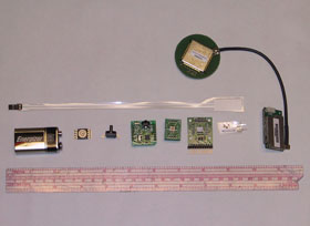
The RDAS flight computer has and will continue to be used for some flight-testing of sensors, and as a back-up in case the Mudd-designed system isn’t ready by January 2008. It has a maximum sample rate of 200 SPS, a 10-bit A-to-D resolution, and just over 300 kB of storage. It has an axial accelerometer, and an altitude pressure sensor. It can be additionally configured with two lateral accelerometers, a temperature sensor, a GPS, and a 900 MHz telemetry system, or with custom-built sensor inputs. We have already successfully flight-tested it with a custom four-channel vibration-sensor board. The RDAS allows a total of six analog inputs beyond the accelerometer and altimeter. Ideally, we want a data acquisition system that allows us more freedom with the measurement resolution and the number of inputs (more sensors), and has higher rates and storage capabilities.
| Part Description |
Part Number |
Manufacturer |
Voltage Req |
Current Req (mA) |
Physical Input |
Output Range |
Bandwidth or Response Rate |
| High-g MEMS accelerometer |
AD22279-A-R2 (ADXL78) |
Analog Devices |
5 |
2 |
Accel. ±35 g |
0.575 to 4.425 V |
400 Hz |
| High-g MEMS accelerometer |
AD22280-R2 (ADXL78) |
Analog Devices |
5 |
2 |
Accel. ±50 g |
0.6 to 4.4 V |
400 Hz |
| Dual axis accelerometer |
ADXL320 |
Analog Devices |
3 to 5 |
1 |
Accel. ±5 g |
0.6 to 2.4 V |
2500 Hz |
| Dual-axis rate gyro |
IDG300 |
InvenSense |
3.0 to 3.3 |
10 |
Ang. Vel. ±500¡/s |
0.5 to 2.5 V |
140 Hz |
| Pressure transducer |
MPXAZ4115A |
Freescale |
5 |
7 |
Pressure 15 to 115 kPa |
0.2 to 4.8 V |
1 ms |
| Diff. pressure transducer |
MPXV7025G |
Freescale |
5 |
7 |
Pressure ±25 kPa |
0.2 to 4.7 V |
1 ms |
| Thermistor |
|
|
|
|
|
|
<1 s |
| Vibration sensor |
FDT1 |
MSI |
N/A |
N/A |
Dynamic Strain |
± 10 V or more |
1 GHz |
| Vibration sensor |
LDT0-028K |
MSI |
N/A |
N/A |
Dynamic Strain |
± 10 V or more |
1 GHz |
| Precision quad op-amp |
AD8608 |
Analog Devices |
5 |
1 |
Voltage 0 to 5 |
.02 to 4.98 V |
10 MHz |
| Precision 2.5 V reference |
REF192 |
Analog Devices |
3.5 to 15 |
0.045 |
N/A |
2.50 V |
N/A |
| Precision 3 V reference |
REF193 |
Analog Devices |
4 to 15 |
0.045 |
N/A |
3.00 V |
N/A |
| Precision 5 V reference |
REF195 |
Analog Devices |
6 to 15 |
0.045 |
N/A |
5.00 V |
N/A |
Navigation Sensors
To determine the trajectory of a three-dimensional body in space, it is necessary to measure three orthogonal axes of acceleration/velocity/position and three axes of angular velocity/orientation. The new MEMS sensors used in devices such as Nintendo's Wii controllers and Apple's iPhone(trademark battle still in progress) provide accelerometers and rate-gyroscopes at remakably low cost. The present plan is to use one of Analog Devices' ADXL78 family for the high-g acceleration along the rocket axis, and an ADXL320 to measure the moderate acceleration in two directions orthogonal to the rocket axis. Two of InvenSense's IDG300s will be used to measure angular velocity in three mutually orthogonal axes. The axial direction will have redundant angular sensing.
In addition, most modern inertial measurement units (IMU) include GPS and possibly magnetic fields. We are evaluating the Garmin GPS 15 (which has a 1 SPS update rate), and the Atmel
ATR0635 (which has a 4 SPS update rate) for use as our GPS sensor, and PNI Corp.'s MicroMag3 for three-axis sensing of the earth's magnetic field.
Model and hobby rockets have long flown pressure sensors to determine altitude. Our chosen pressure sensor is the Freescale MPXAZ4115A, another MEMS device. It is an absolute pressure sensor that will be used for altitude determination. Freescale makes a differential pressure sensor, the MPXV7025G, that we plan on evaluating for suitability in a Pitot-tube-style velocity sensor. It should be able to measure velocities up to 450 MPH.
If we are successful with our data-collection design, we should have enough processing power to combine the outputs from these 13 sensors in a Kalman filter to calculate the acceleration, velocity, location, angular velocity, and orientation of the rocket in real time with a fair degree of accuracy.
We have also begun work on the board-sensor integration. We have purchased various sensor solutions for measurements of pressure, temperature, and vibration. We’ve instrumented one model rocket body with piezoelectric vibration sensors and measured the response of the body when subjected to a tap test. We launched an initial vibration sensor flight test in November 2006. We had telemetry lock on both the on-board video and the on-board sensors (acceleration, pressure-altitude, and vibration) for the entire flight. The results have been posted on the project website (www.eng.hmc.edu/NewE80). We are currently working on the next test launch scheduled for April 2006 in which we will test six vibration sensors simultaneously as well as a carbon-fiber/Kevlar composite body tube. Additional test flights are planned as the design progresses. For the initial test flights, we are using the RDAS system and custom sensor boards.