Lab 6 Specifications
Learning Objectives
By the end of this lab you will have…
- Designed and built a simple IoT device
- Written C libraries using the CMSIS device templates to implement the SPI functionality of the MCU
- Interfaced with a temperature sensor module over an SPI link
- Interfaced the MCU with an ESP8266 module over a UART link
- Use the logic analyze functionality of the scope in the Digital Lab to debug serial communication protocols and export captured signal data.
- Written a simple HTML page to control and display data from the peripherals connected to your MCU.
Requirements
Build an internet-accessible device to control an onboard LED and measure ambient temperature. Use an ESP8266 with the provided web server code to host the webpage and use the onboard MCU GPIO and SPI peripherals to toggle an LED and to read temperature from a provided sensor chip. An end-user must be able to turn the LED ON and OFF and view the current temperature from the webpage.
In addition to the standard deliverables in your report (summary, schematic, etc.), your report also must include an example of a SPI read/write interaction with all pertinent data signals (e.g., CE, SCK, SDO, SDI) captured using the logic analyzer functionality of the oscilloscopes in the Digital Lab.
At heart, this lab asks you to consult the MCU documentation to learn how to directly control the SPI memory-mapped peripheral on the MCU, so refrain from consulting any other C device drivers that can be found on the web or elsewhere.
Note that for this lab your SPI device driver must use the Common Microcontroller Software Interface Standard (CMSIS) device templates included in the stm32l432xx.h device header. See the provided example device drivers on the course GitHub repository for an example. The GPIO driver provides a good example of how to use the information included in the CMSIS headers.
Note: There are only a limited number of ESP8266 boards and DS1722 SPI temperature sensors available for this lab. Please do not remove these devices from the digital lab so that everyone can access these shared resources.
Resources
Specs
Open specifications in new tab.
Lab-specific Specifications
Proficiency
Excellence
General Specifications
Proficiency
General Schematic Specifications
Block Diagram
HDL & Code Specifications
General Formatting
Comments
Lab Writeup/Summary
Excellence
General Schematic Specifications
HDL & Code Specifications
General Formatting
Testbenches
Lab Writeup/Summary
ESP8266 Web Server
Broadly speaking, everything that you see on the internet is the product of one computer presenting text to another. The text is often formatted in a special, internet-specific, way that includes information about how to display it which is referred to as hypertext. (Forgive the early internet engineers for this indulgence; I’m sure it sounded really cool at the time.) Hypertext is specified using a compact programming language called hypertext markup language or HTML. It is transferred over the internet based on a predefined set of agreements between all computers which is referred to as the hypertext transfer protocol or HTTP. The latter most of these acronyms should be familiar: whenever you type http:// into a web browser you are informing your computer that you are attempting to retrieve hypertext from the address that follows.
There are two common tools that interact with HTTP: the web browser, which lives on a receiving computer, sends internet requests, and renders the received hypertext; and the web server, which listens for requests from the internet and sends out hypertext in response.
Implementing an HTTP web server on the ARM microcontroller is a non-trivial task. Instead, you will be using an ESP8266, a small WiFi development board which incorporates a TCP/IP stack as well as onboard WiFi and an integrated antenna. You are provided an Arduino language program which hosts an HTTP web server with an HTML page generated by the MCU.
ESP8266-MCU Interface
Download the Lab 6 starter code and support files from the class web page. You may use any code we have developed in class to help you write your code.
ESP8266 development boards are available from the E155 supply closet and are pre-programmed with the webserver code. The SSID for the WiFi access points associated with each board is Lab6_ESP_xx where xx is the number listed on each board.
The ESP8266 board requires 3.3 V power. However, it has an onboard regulator so you can power the board with between 3-6 V using the V+ and GND pins. If after supplying power to the chip and waiting for it to initialize you do not see the expected WiFi network appear, you may need to reprogram the chip with the provided code.
The MCU must supply a webpage to the ESP8266, and must interpret any web browser requests from the ESP8266. The devices interface through a 125000 baud serial UART connection on the MCU and the UART TX and RX lines of the ESP8266. Note that with a UART connection the receive and transmit lines should be crossed. In other words, the TX of the transmitter should be connected to the RX of the receiver and the RX of the transmitter should be connected to the TX of the receiver.
The protocol is as follows:
- When the ESP8266 updates the webpage from the MCU, it sends the most recent request from the client, within
/REQ:'...'\n. For example, a user accessing the pagehttp://<server_address>/ledonwould result in the request/REQ:ledonnbeing sent to the microcontroller. A user accessing the root webpage of the server,http://<server_address>/would result in the request/REQ:\n. Note that you must usehttp://and nothttps://. - The MCU then transmits the entire web page to the ESP8266. The ESP8266 expects a webpage encoded as an HTML file. Therefore the webpage must start with ‘<!DOCTYPE html><html>’ and end with ‘</html>’. The ESP will wait for either </html> or 200 ms from the last byte sent over serial before terminating the HTTP request and forwarding the content to the web browser.
The ESP8266 will create a WiFi access point named whatever SSID is labeled on the board. Connect to this WiFi network, and then go to http://192.168.4.1/. Beware that the ESP is slow and it may sometimes take a few attempts to connect.
Digital Temperature Sensor
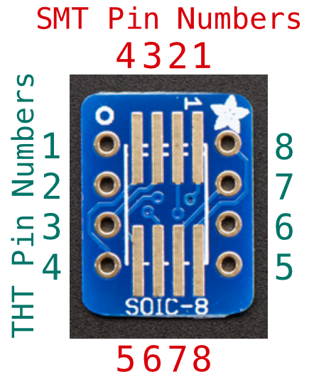
The temperature sensor you will interface with for this lab is the DS1722 Digital Thermometer with SPI/3-Wire Interface from Maxim Integrated. This chip is an example of a simple peripheral that supports an SPI interface. You will need to get a DS1722 chip from the E155 stock cabinet mounted on an SOIC-8 breakout board. There are some boards that are already soldered, but if you are unable to find any pre-soldered boards to use, there may also be some chips and extra breakout boards you can solder yourself. After getting a board, consult the DS1722 datasheet to correctly wire up the device. Make sure to thoroughly read the data sheet and refer to the pinout before attempting to interface with the device!
The figure below shows the corresponding pinout between the SMT pads and the header pins on the breakout board for your convenience.
MCU Hardware and the Internet of Things
The last component of this lab is to write a program that parses a request from the ESP8266, toggles the LED state as necessary, reads from the SPI temperature sensor, and uses this data to generate a webpage that is transmitted to the ESP8266. Make sure that the FPGA code on your board does not interfere with any of the pins which you may want to use for your sensors or else you will experience undefined behavior.
You will need to write an HTML webpage that displays dynamic temperature data as well as creating requests to change the state of the LED. There are many ways to do this, but we suggest the following resources for information on HTML formatting and interactive elements:
The final product of this lab is a simple example of an emerging class of devices called the Internet of Things. Proponents of these devices argue that everything—from your washing machine to your car to giant factories—should be connected to the internet so that the shared data can be used to optimize and improve societal functions. Internet-controlled lighting, and internet-accessible sensors are two promising domains for the field, and are exemplified in this lab.
Hints
The time spent on this lab has been highly variable in the past. If SPI doesn’t work on your first try, it can take a long time to debug because there are many different settings, all of which have to be correct. You can increase the chance of SPI working by carefully studying the MCU documentation before coding. Before connecting the peripheral device, look at the SPI outputs on a logic analyzer and make sure that the clock, SDO, and the chip enables are matching your expectations. Fix your code if they do not. Then attach the peripheral and recheck all the signals including SDI.
What to Turn In
When you are done, have your lab checked off by the instructor. You should thoroughly understand how it works and what would happen if any changes were made. Turn in your lab writeup including the following information:
- Schematics of the breadboarded circuit.
- A screen capture (exported from the scope, not a photo captured using a camera) of an example SPI transaction captured on the oscilloscope/logic analyzer.
- Your source code.
- How many hours did you spend on the lab? This will not count toward your grade.