If the input voltage to the RC circuit considered previously is
sinusoidal
 , then the DE becomes
 |
(146) |
The homogeneous solution is the same as before
 .
To find the particular solution
  as the steady state response
to the input
 , we first assume the input is
 , and the particular solution is
 and
and
 . The DE can now be written as
 |
(147) |
Solving for  we get
 |
(148) |
Substituting  back into
  we get
 |
(149) |
where
 . Taking the real part of the above
we get the particular solution as the response to the actual input

![$\displaystyle y_p(t)=Re\left[\frac{V_s e^{j(\omega t+\psi-\phi)}}{j\omega\tau+1}\right]
=\frac{V_s}{\sqrt{(\omega\tau)^2+1}}\cos((\omega t+\psi-\phi)$](img451.svg) |
(150) |
Alternatively, we can also use the phasor method. The input can be
written as
![$\displaystyle v(t)=V_s \cos(\omega t)=Re[\dot{V} e^{j\omega t}]$](img452.svg) |
(151) |
where
 is the phasor form of the input voltage.
The voltage across
  is (voltage divider):
where
 , and
, and  is the
frequency response function (FRF) of the system:
 |
(153) |
In time domain the steady state voltage  is:
is:
Note that this steady state output is simply the
input
 scaled by the magnitude of the FRF
 with a phase shift equal to the
phase of the FRF
 .
.
We get the complete solution as the sum of the homogeneous and
particular solutions:
 |
(155) |
From the initial condition
 , we have
 |
(156) |
Solving for  we get
 |
(157) |
Substituting  back to the expression of
  , we get
![$\displaystyle v_C(t)=\frac{V_s}{\sqrt{(\omega \tau)^2+1}}\cos(\omega t+\psi-\ph...
...left[V_0-\frac{V_s}{\sqrt{(\omega \tau)^2+1}}\cos(\psi-\phi)\right] e^{-t/\tau}$](img467.svg) |
(158) |
The same result can also be obtained using the
Laplace transform method.
Again we consider a short-cut method, by generalizing the result above to
![$\displaystyle f(t)=f_{\infty}(t)+[f(0)-f_{\infty}(0)]e^{-t/\tau}$](img468.svg) |
(159) |
in terms of three essential components
 : the initial value (same as before);
-
 : the steady state response, and
 is
is
 evaluated
at
  ;
;
 : the time constant of the system (same as before).
Note that when the input  is a constant, the steady state response
 is a constant, but when the input
 is sinusoidal, the steady state response
 is a function of
time
  , but its evaluation at
 is still a constant. We see that the complete response is composed of
the steady state response and the exponential decay of the difference
between the initial value
  and the steady state response evaluated
at
  .
.
If the initial voltage on  is zero
  , then
![$\displaystyle v_C(t)=\frac{V_s}{\sqrt{(\omega \tau)^2+1}}[\cos(\omega t+\psi-\phi)
-\cos(\psi-\phi) e^{-t/\tau}]$](img472.svg) |
(160) |
Note that the initial magnitude of the transient component at  varies depending on the angle
  .
.
- If
 , then
 , and the
transient component disappears altogether.
- If
 or
or  , then
 ,
i.e., the magnitude of the transient component reaches maximum (either
positive or negative), and if
  value is large and therefore the
transient component decays slowly, the magnitude of the initial voltage
 could be close to three times the peak of the steady state.
- In all other cases, the amplitude of the transient component is
between 0 in the first case and the maximum value in the second case.
The three cases for  to be
to be  ,
,  , and
, and  are shown below:
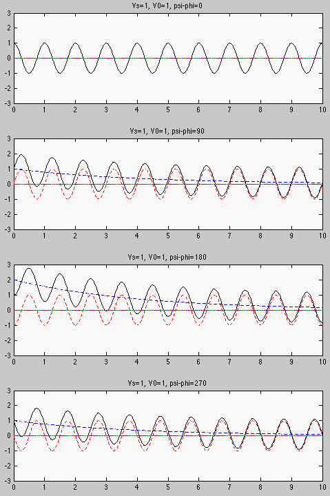
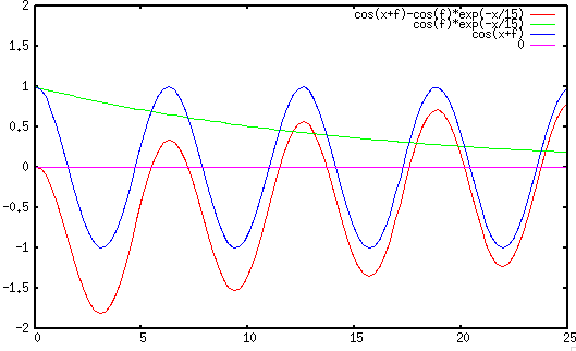
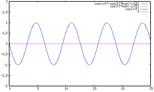
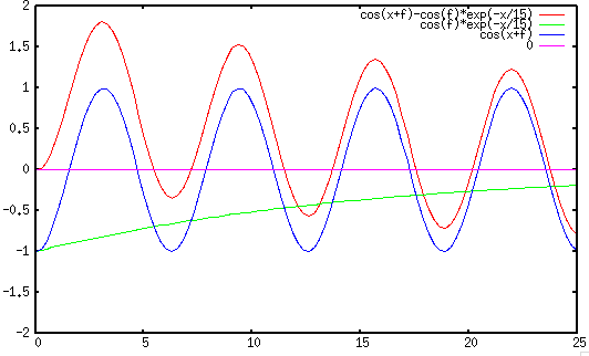
Example 2:
An electromagnet, modeled by a resistor
 and
and  ,
is powered by sinusoidal voltage of
  and
and  . Find the current
through the circuit when the switch is closed at
  when the phase
angle happens to be
 , i.e.,
 .
.
- Find initial value:
 .
.
- Find impedance of circuit:
 |
(161) |
- Find steady state value
 by phasor method:
 |
(162) |
 |
(163) |
 |
(164) |
- Find time constant
 .
.
- Find current
![$\displaystyle i(t)=i_{\infty}(t)+[i(0)-i_{\infty}(0)]e^{-t/\tau}
=1.05\sqrt{2}\;\cos(6.28\times 60 t -70^\circ)-0.51 e^{-t/0.015}$](img493.svg) |
(165) |
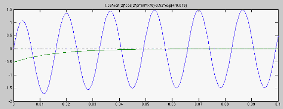


 .
To find the particular solution
  as the steady state response
to the input
 , we first assume the input is
 , and the particular solution is
 and
and
 . The DE can now be written as

 we get

 back into
  we get

 . Taking the real part of the above
we get the particular solution as the response to the actual input

![$\displaystyle y_p(t)=Re\left[\frac{V_s e^{j(\omega t+\psi-\phi)}}{j\omega\tau+1}\right]
=\frac{V_s}{\sqrt{(\omega\tau)^2+1}}\cos((\omega t+\psi-\phi)$](img451.svg)
![$\displaystyle v(t)=V_s \cos(\omega t)=Re[\dot{V} e^{j\omega t}]$](img452.svg)
 is the phasor form of the input voltage.
The voltage across
  is (voltage divider):


 , and
, and  is the
frequency response function (FRF) of the system:

 is:
is:


![$\displaystyle Re\left[\dot{V}_C e^{j\omega t} \right]
=Re\left[ \frac{V_s e^{j(...
...)^2+1}} \right]
= \frac{V_s}{\sqrt{(\omega \tau)^2+1}} \cos(\omega t+\psi-\phi)$](img459.svg)


 scaled by the magnitude of the FRF
 with a phase shift equal to the
phase of the FRF
 .
.

 , we have

 we get

 back to the expression of
  , we get
![$\displaystyle v_C(t)=\frac{V_s}{\sqrt{(\omega \tau)^2+1}}\cos(\omega t+\psi-\ph...
...left[V_0-\frac{V_s}{\sqrt{(\omega \tau)^2+1}}\cos(\psi-\phi)\right] e^{-t/\tau}$](img467.svg)
![$\displaystyle f(t)=f_{\infty}(t)+[f(0)-f_{\infty}(0)]e^{-t/\tau}$](img468.svg)
 : the initial value (same as before);
 : the steady state response, and
 is
is
 evaluated
at
  ;
;
 : the time constant of the system (same as before).
 is a constant, the steady state response
 is a constant, but when the input
 is sinusoidal, the steady state response
 is a function of
time
  , but its evaluation at
 is still a constant. We see that the complete response is composed of
the steady state response and the exponential decay of the difference
between the initial value
  and the steady state response evaluated
at
  .
.


![$\displaystyle v_C(t)=\frac{V_s}{\sqrt{(\omega \tau)^2+1}}[\cos(\omega t+\psi-\phi)
-\cos(\psi-\phi) e^{-t/\tau}]$](img472.svg)


 , then
 , and the
transient component disappears altogether.
 or
or  , then
 ,
i.e., the magnitude of the transient component reaches maximum (either
positive or negative), and if
  value is large and therefore the
transient component decays slowly, the magnitude of the initial voltage
 could be close to three times the peak of the steady state.


 .
.

 by phasor method:


 .
.
![$\displaystyle i(t)=i_{\infty}(t)+[i(0)-i_{\infty}(0)]e^{-t/\tau}
=1.05\sqrt{2}\;\cos(6.28\times 60 t -70^\circ)-0.51 e^{-t/0.015}$](img493.svg)
