Next: Complete Response II – Up: First Order Systems Previous: Particular Solution
The complete response of a non-homogeneous linear system due to both the external input and the initial condition can be found as the sum of the homogeneous and particular solutions of the non-homogeneous DE with a non-zero right-hand side for the external input:
Complete Solution Homogeneous Solution Homogeneous Solution Particular Solution Particular Solution |
(107) |
For the RC circuit, we have
 |
(108) |
 as the circuit's complete response to the
input
as the circuit's complete response to the
input  as well as the initial condition
 , after a
switch is closed at time moment
, after a
switch is closed at time moment  .
.

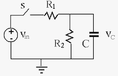
Given an RC circuit shown above where the switch is closed at ,
we want to find the voltage across  and voltage
  across
  as a function of time for
  .
.
First we consider a constant (DC) input  applied to the circuit
at , i.e., a step input
applied to the circuit
at , i.e., a step input
 |
(109) |
 due to the initial condition
 .
.
 due to the DC input
  .
Or by phasor method, we can get
.
Or by phasor method, we can get
 |
(110) |
The complete solution is sum of the homogeneous and particular solutions:
 |
(111) |
 can then be determined from the initial condition
 :
:
 i.e., i.e., |
(112) |
 |
(113) |
,

 ,
,

 , decays exponentially from
  to .
to .
We can further find the current through :
 |
(114) |
:
 |
(115) |
 |
(116) |
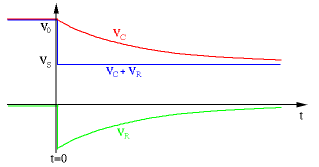
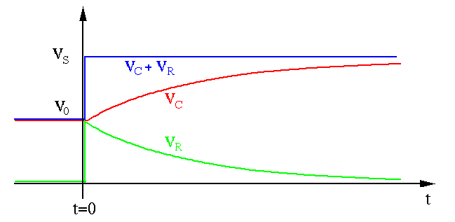
The plots below show (red) and (green) under different
initial conditions (purple) and inputs (blue).
 ,
,  , i.e.,
 ,
,  , i.e.,
Note that in the first case, after the switch is closed at ,
takes a negative value if
 for , although
the voltage source
for , although
the voltage source  is positive (both measured with respective to
the bottom wire treated as the ground). This is because right after the
switch is closed, the voltage on the left side of drops from
is positive (both measured with respective to
the bottom wire treated as the ground). This is because right after the
switch is closed, the voltage on the left side of drops from
 to
to  , causing the voltage on its right side to also drop
from 0 to
, causing the voltage on its right side to also drop
from 0 to  , lower than the ground level of
  .
go through a discontinuous transition to
drop (case 1) or jump (case 2) by
.
go through a discontinuous transition to
drop (case 1) or jump (case 2) by  , however, the voltage
remains the same, as the voltage across does not change instantaneously.
drops from
, however, the voltage
remains the same, as the voltage across does not change instantaneously.
drops from  for
for  to
to
 at
at
 , while
 (left side of ) drops from to
  .
.
In general, neither the voltage across a capacitor nor the current through an inductor can be changed instantaneously as it takes time for them to build up:
 |
(117) |
Example 0 (homework): When an RC circuit with zero initial voltage
 is charged by a DC voltage . Find energy
  is consumed
by and energy
is consumed
by and energy  is stored in .
A Shortcut Method:
Observing the complete solution
 obtained
above, we see that
obtained
above, we see that
,
 is the initial condition
,
is the initial condition
,
 is the steady
state response.
is the steady
state response.
We can therefore generalize the complete solution obtained above to all
first-order systems, i.e., their responses to a step input, a constant input
that is turned on at moment , always take the same form:
![$\displaystyle f(t)=f(\infty)+[f(0)-f(\infty)] e^{-t/\tau}$](img358.svg) |
(118) |
 : as discussed in previous
section for steady state response.
: as discussed in previous
section for steady state response.
 :
Denote the value of
:
Denote the value of  immediately before and after the moment
by
immediately before and after the moment
by  and
and  , respectively. If
 ,
then use for ;
,
then use for ;
 : When there is only one
resistor in the circuit, the time constant is
: When there is only one
resistor in the circuit, the time constant is  or
or  .
When there are multiple resistors, the time constant can be found by:
or
.
When there are multiple resistors, the time constant can be found by:
or  so that the rest of the circuit () is a
one port network.
of the network by turning off
all energy sources (short-circuit for voltage source, open-circuit
for current source).
or .
so that the rest of the circuit () is a
one port network.
of the network by turning off
all energy sources (short-circuit for voltage source, open-circuit
for current source).
or .
In particular, note that
,
 the initial condition;
,
the initial condition;
,
 the steady state response;
, the difference
the steady state response;
, the difference
 between the initial
and the steady state values of the response decays exponentially. This term is
the transient response of the system.
between the initial
and the steady state values of the response decays exponentially. This term is
the transient response of the system.
Example 1:
 ,
,
 ,
,
 ,
,
 . Find .
.
 :
:
 |
(119) |
:
 |
(120) |
 |
(121) |
![$\displaystyle v_C(t)=v_C(\infty)+[v_C(0)-v_C(\infty)]e^{-t/\tau}
=1+(2-1)e^{-t/10^{-3}}=1+e^{-1000\,t}$](img376.svg) |
(122) |
![$\displaystyle v_C(0)=\left[1+e^{-1000\,t}\right]_{t=0}=2,\;\;\;\;\;
v_C(\infty)=\left[1+e^{-1000\,t}\right]_{t=\infty}=1$](img377.svg) |
(123) |
Example 2:
In the circuit below,  ,
,
 ,
,
 ,
,
 , the circuit is in steady state when . Find
after the switch is closed at .
, the circuit is in steady state when . Find
after the switch is closed at .
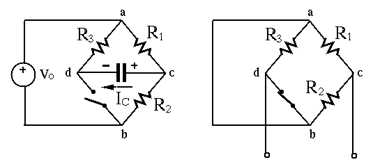
Consider node voltage method. Applying KCL to node  we get
 |
(124) |
 |
(125) |
 |
(126) |
 , we assume the circuit is in
steady state before , i.e.,
, we assume the circuit is in
steady state before , i.e.,
 . Also, as the
voltage across does not change instantaneously (unless
. Also, as the
voltage across does not change instantaneously (unless
 therefore
  ), we have
 .
At
.
At  ,
,  drops from
  to
to  ,
,  also drops
from
also drops
from  to
to  .
.
The homogeneous solution is
and the particular
(steady state) solution is
 . The complete solution
is
. The complete solution
is
 |
(127) |
The coefficient can be found by equating  evaluated
at and the initial condition
evaluated
at and the initial condition
 :
:
 |
(128) |
 . Now the solution is
 |
(129) |
Example 3:
Resolve the circuit above using the short-cut method:
 ,
same as that found previously;
:
,
same as that found previously;
:
 |
(130) |
:
|
(131) |
 |
(132) |
![$\displaystyle v_C(t)=v_C(\infty)+[v_C(0)-v_C(\infty)]e^{-t/\tau}
=5+(-5-5) e^{-t/0.0005}=5-10 e^{-2000t}\;(V)$](img406.svg) |
(133) |
![$\displaystyle v_C(0)=\left[5-10 e^{-2000t}\right]_{t=0}=-5,\;\;\;\;\;
v_C(\infty)=\left[5-10 e^{-2000t}\right]_{t=\infty}=5$](img407.svg) |
(134) |
 through :
 |
|
 |
|
|
 |
(135) |
 and
and  across
  and
and  ,
respectively:
,
respectively:
 |
(136) |
 |
(137) |
 and
and  through and ,
respectively:
through and ,
respectively:
 |
(138) |
 |
(139) |
:
 |
(140) |
Example 4:
In the same circuit above, find the voltages and
across and currents and through and ,
respectively.

 and
and  . Before , the circuit is in
steady state, i.e.,
. Before , the circuit is in
steady state, i.e.,
 . However, after
the switch closes at , the voltage at node d drops from
10V to 0V (with respect to node b as ground), and the voltage
at node c drops from 5V to -5V (voltage across a capacitor
cannot change instantaneously), i.e.,
. However, after
the switch closes at , the voltage at node d drops from
10V to 0V (with respect to node b as ground), and the voltage
at node c drops from 5V to -5V (voltage across a capacitor
cannot change instantaneously), i.e.,
 and
and
 ;
;
 (same as before);
and :
(same as before);
and :
![$\displaystyle v_1(t)=v_1(\infty)+[v_1(0_+)-v_1(\infty)]e^{-t/\tau}
=5+(15-5)e^{-t/\tau}=5+10e^{-t/\tau}\;V$](img428.svg) |
(141) |
![$\displaystyle v_2(t)=v_2(\infty)+[v_2(0_+)-v_2(\infty)]e^{-t/\tau}
=5+(-5-5)e^{-t/\tau}=5-10e^{-t/\tau}\;V$](img429.svg) |
(142) |
 for all
  .
and through and :
.
and through and :
 |
(143) |
 |
(144) |
through capacitor :
 |
(145) |
,
 , lower than ground voltage
  !
!
We see that
 and
and
 .
.