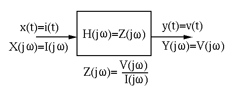
Next: First Order Systems Up: Chapter 3: AC Circuit Previous: Phasor Representation of Sinusoidal
Impedance of Basic Components
In time domain, the relationship between the sinusoidal current through and the sinusoidal voltage across a capacitor or an inductor is described by a differential equation. However, in frequency domain, where these sinusoidal variables are represented as complex exponentials, and the components such as R, C, and L are all represented by their impedances, then the relationship between the sinusoidal voltage and current can be described by an algebraic equation.
Specifically, we represent the sinusoidal voltage and current as the projection of the corresponding vector in the complex plane rotating counter-clock wise onto the real axis:
![$\displaystyle v(t)=V_p\cos(\omega t+\phi)=Re[ V_p e^{j(\omega t+\phi)} ],
\;\;\;\;\;\;\;\;
i(t)=I_p\cos(\omega t+\psi)=Re[ I_p e^{j(\omega t+\psi)} ]$](img102.svg) |
(33) |
Impedance |
(34) |
 |
(35) |
 , we have
 |
(36) |
 |
(37) |
![$\displaystyle i(t)=I_pe^{j(\omega t+\psi)}=C\frac{dv}{dt}
=C\frac{d}{dt}[V_p e^{j(\omega t+\phi)}]
=j\omega C V_p e^{j(\omega t+\phi)}$](img108.svg) |
(38) |
 |
(39) |
 |
(40) |
 ,
i.e., the voltage lags behind the current by
,
i.e., the voltage lags behind the current by  , or the current
leads the voltage by (“ICE”).
, or the current
leads the voltage by (“ICE”).
![$\displaystyle v(t)=V_pe^{j(\omega t+\phi)}=L\frac{di}{dt}
=L\frac{d}{dt}[I_p e^{j(\omega t+\psi)}]
=j\omega L I_p e^{j(\omega t+\psi)}$](img112.svg) |
(41) |
 |
(42) |
 |
(43) |
 ,
i.e., the voltage leads the current by (“ELI”).
,
i.e., the voltage leads the current by (“ELI”).
 and current
  associated with capacitor
  and inductor
  is “ELI the ICE man”.
Also, consider two extreme cases:
is “ELI the ICE man”.
Also, consider two extreme cases:
 ,
,
 and the capacitor has zero
conductivity due to the insulation between its two plates (open circuit),
and
and the capacitor has zero
conductivity due to the insulation between its two plates (open circuit),
and  as there is no flux change in the inductor and the resistance
of the coil is ideally zero.
as there is no flux change in the inductor and the resistance
of the coil is ideally zero.
 ,
,
 and the capacitor
becomes highly conductive, and
and the capacitor
becomes highly conductive, and
 as the self-induced
voltage in the coil always acts against any change in the input (Lenz's Law).
as the self-induced
voltage in the coil always acts against any change in the input (Lenz's Law).
In a DC circuit, each resistor is measured by either its resistance  or its conductance
  . In an AC circuit each component (capacitor,
inductor, or resistor) is measured by its impedance
. In an AC circuit each component (capacitor,
inductor, or resistor) is measured by its impedance  , of which the
real and imaginary parts are respectively the resistance and reactance
, of which the
real and imaginary parts are respectively the resistance and reactance
 , or its admittance
  , of which the real and imaginary parts are
respectively the conductance
, of which the real and imaginary parts are
respectively the conductance  and susceptance
  , as summarized below:
As a complex variable, the impedance can be written in either
Cartesian or polar form:
 |
(44) |
![$Re[Z]=R$](img133.svg) is called resistance.
is called resistance.
![$Im[Z]=X$](img134.svg) is called reactance.
is called reactance.
 ).
).
The magnitude and phase angle of are:
 |
(45) |
 associated with and
 are both purely imaginary, i.e., they are both reactance,
indicating these components are reactive and consume no energy.
are both purely imaginary, i.e., they are both reactance,
indicating these components are reactive and consume no energy.
The reciprocal of the impedance is called admittance:
 |
(46) |
![$\displaystyle G=Re[Y]=\frac{R}{R^2+X^2} \ne \frac{1}{R}$](img140.svg) |
(47) |
![$\displaystyle B=Im[Y]=\frac{-X}{R^2+X^2} \ne \frac{1}{X}$](img141.svg) |
(48) |
 ).
).
The magnitude and phase of complex admittance are
 |
(49) |
 |
(50) |
Impedance and admittance are both complex variables. The
real parts and ![$Re[Y]=G$](img145.svg) are always positive, but the imaginary
parts and
are always positive, but the imaginary
parts and ![$Im[Y]=B$](img146.svg) can be either positive or negative. Therefore
and
can be either positive or negative. Therefore
and  can only be in the 1st or the 4th quadrants of the complex plane.
In particular, the admittances of the three types of elements R, L and C are
 |
(51) |
Ohm's law can also be expressed in terms of admittance as well as impedance. Sometimes it is more convenient in circuit analysis to use admittance instead of impedance.
 |
(52) |
 |
(53) |
Generalized Ohm's law and Kirchhoff's Laws
In general, all methods such as Ohm's law and Kirchhoff's Laws used for DC
circuits composed of resistors can be generalized to AC circuits composed
of capacitors, inductors, as well as resistors, all represented by their
impedances. Also, if we assume all voltages and currents in a circuit are
sinusoids of same frequency  , they can be represented as complex
phasors.
, they can be represented as complex
phasors.
The Ohm's law can be generalized to become:
 |
(54) |
 .
.
 .
.
Solving AC circuit by phasor method
If only the steady state solutions of the DE describing an AC circuit is of interest, the phasor method can be used to solve the problem algebraically without solving the DEs. Specifically, all sinusoidal variables are represented as phasors in terms of their amplitudes and phases, and all components in the circuit (L and C, as well as R) are represented by their impedances, so that all the laws (Ohm's law, KCL and KVL, current and voltage dividers, parallel and series combinations of components) and methods (loop current and node voltage methods, Thevenin's and Norton's theorems, etc.) discussed for DC circuit can be applied.
Operations on sinusoidal variables based on the trigonometric identities are in general lengthy and tedious. The phasor method can convert such sinusoidal variables to vectors in complex plane and thereby simplify the operations.
Here is a review of complex arithmetic.
Example 1:
Solve the circuit below. The voltage from the generator is
 .
.
The given voltage  can be expressed
in phasor form as
can be expressed
in phasor form as
 |
(55) |
First find the impedances and admittances of the components and the
two branches. As
 , we get


![$i_{load}(t)=Re[\dot{I} e^{j5000t}]=Re[(1\,e^{j\,90^\circ}) e^{j5000t}]
=\cos(5000t+90^\circ)$](img167.svg)

![$i_C(t)=Re[ (1.41 e^{j 135^\circ}) e^{j5000t}]=1.41\;\cos(5000t+135^\circ)$](img169.svg)

![$i_{RL}(t)=Re[ e^{j0} e^{j5000t} ]=\cos(5000t)$](img171.svg)


Example 2:
A current
 flows through a circuit composed of a resistor
 , a capacitor
 , and an inductor
 connected in series. Find the resulting voltage across all
three elements.
connected in series. Find the resulting voltage across all
three elements.
 in phasor:
 .
.
 ):
):
 |
(56) |
 |
(57) |
 |
(58) |
 |
(59) |
 |
 |
 |
|
 |
|
 |
|
 |
|
 |
(60) |
 |
|
 |
|
 |
|
 |
|
 |
|
 |
(61) |
 ,
,  , and
, and  , we get the total voltage
which is the same as what we got above:
, we get the total voltage
which is the same as what we got above:
 |
(62) |
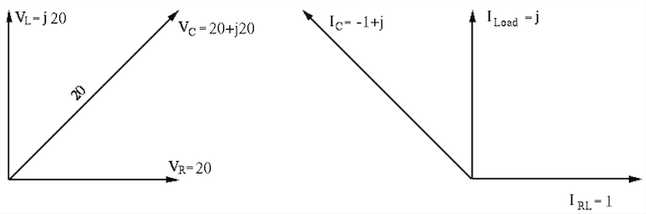
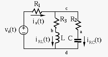
Example 3:
In the circuit below,
 with some unknown peak value
  ,
,
 , and
, and
 . The RMS value of
  across
  is 10 V. It
is also known that
is 10 V. It
is also known that  and
and  are in phase.
.
 and
and  .
.
 and
and  .
of .
.
of .
Solution
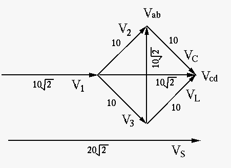
We first note that is behind
 by
by  , and is ahead of
 by (“ELI the ICE man”). Also, as and
are in phase, the parallel combination of the RL and RC branches
introduces no phase shift, i.e., its impedance shown below must be
real:
by (“ELI the ICE man”). Also, as and
are in phase, the parallel combination of the RL and RC branches
introduces no phase shift, i.e., its impedance shown below must be
real:
 |
(63) |
 . We therefore get
 and
and
 ,
,
 ,
,
 ,
,
 , i.e.,
 |
(64) |
 ,
,
 .
But as they are apart in phase, we have
.
But as they are apart in phase, we have
 , and from the
vector diagram
, and from the
vector diagram
 . We also get the currents
through RC and RL branches are:
. We also get the currents
through RC and RL branches are:
 |
(65) |
, we have
 |
(66) |
 is
is
 , and
, and
 |
(67) |
