Next: Wien bridge Up: Chapter 6: Active Filter Previous: The Sallen-Key filters
The twin-T filter
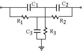
The twin-T network is composed of two T-networks:
 and one
capacitor
and one
capacitor  .
.
 and one
resistor
and one
resistor  .
.
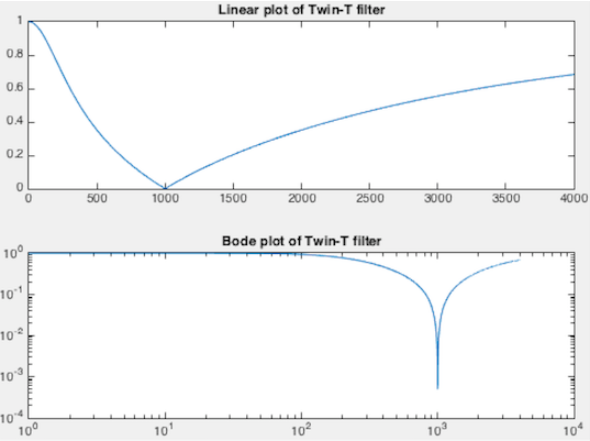
By simple observation we see that when the output is an open-circuit with
 , a sinusoidal signal can pass the twin-T when the frequency
is either very low
, a sinusoidal signal can pass the twin-T when the frequency
is either very low
 or very high
 .
More specifically, the frequency response function of the twin-T network
can be found to be (see here):
.
More specifically, the frequency response function of the twin-T network
can be found to be (see here):
 |
 |
 |
|
|
 |
(36) |
 (37)
(37)
 to zero:
 (38)
(38)
This result can also be reached by noticing the following
 (39)
(39)
When this notch filter is used in a negative feedback loop of an amplifier, it becomes an oscillator.
The active twin-T filter
The bandwidth
 may not be narrow
enough for most applications due to the small quality factor
may not be narrow
enough for most applications due to the small quality factor  .
To overcome this problem, an active filter containing two op-amp
followers (with unity gain
.
To overcome this problem, an active filter containing two op-amp
followers (with unity gain  ) can be used to introduce a positive
feedback loop as shown below:
) can be used to introduce a positive
feedback loop as shown below:
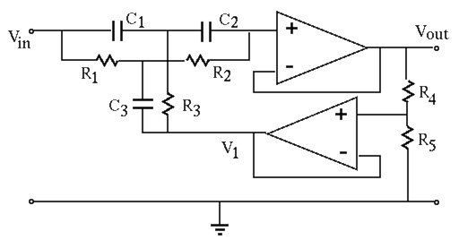
Now the common terminal of the twin-T filter is no longer grounded,
instead it is connected a potentiometer, a voltage divider composed
of  and
and  , to form a feedback loop by which a fraction of the
output
, to form a feedback loop by which a fraction of the
output  is fed back:
 (40)
(40)
 , i.e.,
 .
.
The input and output of the twin-T network are respectively  and
and
 , and they are now related by the frequency response function
 of the twin-T network:
 (41)
(41)
 , we get
 |
|
 |
|
|
 |
(42) |
 (43)
(43)
 we get
 |
|
 |
|
|
 |
||
|
 |
||
|
 |
(44) |
 (45)
and , the bandwidth
(45)
and , the bandwidth
 can be adjusted. In particular,
 ,
,  (no feedback),
 ,
;
,
;
 ,
,  (one hundred percent feedback),
 ,
,
 .
.
The bridged T filter
If in the RCR T-network the vertical capacitor branch is dropped,
i.e.,  , the twin-T network becomes a bridged T network. Now
we have
, the twin-T network becomes a bridged T network. Now
we have  , while the CRC T-network is still the same with
 , we get:
 (46)
(46)
|
|
 |
|
|
 |
||
|
 |
(47) |
 , and express both the numerator and the
denominator in the canonical form as
, and express both the numerator and the
denominator in the canonical form as
 (48)
(48)
 (49)
(49)
 ,
,
 ,
, 
 ,
,
