Next: Colpitts Oscillators Up: ch4 Previous: Multi-stage Amplification
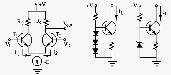
Differential amplifier amplifies the difference
 between two voltages
  and
and  . Differential amplification has
many applications, such as the first stage of
operational amplifiers (Op-amps).
. Differential amplification has
many applications, such as the first stage of
operational amplifiers (Op-amps).
The two transistors  and
and  in the circuit are identical with
the same properties, and their emitters are connected to a current source
with constant current so that
in the circuit are identical with
the same properties, and their emitters are connected to a current source
with constant current so that
 . If
. If  increases,
  will decrease, and vice versa. Consider these three cases:
 , i.e.,
 ,
then
,
then
 and the output voltage is
 , which
is treated as a reference level corresponding to
, which
is treated as a reference level corresponding to
 .
and become higher/lower, and
are driven to go higher/lower, but as their sum
.
and become higher/lower, and
are driven to go higher/lower, but as their sum
 is a
constant, they remain the same and so does the output
is a
constant, they remain the same and so does the output  .
becomes higher but remains the same, the following
changes take place:
.
becomes higher but remains the same, the following
changes take place:
 |
(127) |
becomes higher but remains the same, the following
changes take place:
 |
(128) |
and , but it remains unchanged if both inputs become
higher or lower, i.e., this is a differential amplifier. The output
voltage can be further amplified by the subsequent circuit.
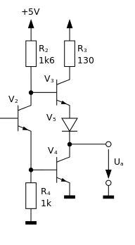
A simple current source is also shown in the figure. The base voltage
 of the transistor is fixed at approximately
 ,
so that the load current
,
so that the load current
 is also approximately constant,
independent of the load, i.e., the circuit can be used as a current source
providing a current determined by but independent of the load. A
better way to hold constant is to replace the diodes by a reverse biased
Zener diode.
When a zener diode is reversely biased by a voltage exceeding its
breakdown voltage, the voltage drop across it, in the circuit,
is held at the breakdown voltage, a constant value independent of any
other variables in the circuit. Consequently
is also approximately constant,
independent of the load, i.e., the circuit can be used as a current source
providing a current determined by but independent of the load. A
better way to hold constant is to replace the diodes by a reverse biased
Zener diode.
When a zener diode is reversely biased by a voltage exceeding its
breakdown voltage, the voltage drop across it, in the circuit,
is held at the breakdown voltage, a constant value independent of any
other variables in the circuit. Consequently  is also constant.
The current mirror circuit shown below is a simple current source
that provides a constant current independent of the load  .
.
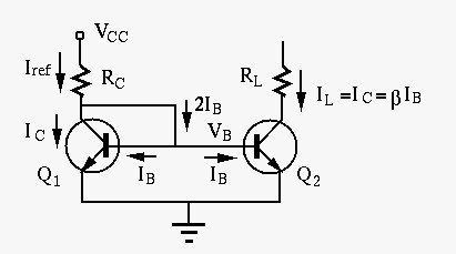
This circuit is composed of two matching transistors  and
and  with identical behaviors such as the input and output characteristics
and
with identical behaviors such as the input and output characteristics
and
 . They are the input and output stages of
the circuit, respectively. As the input, the reference current
. They are the input and output stages of
the circuit, respectively. As the input, the reference current  can be determined as
 |
(129) |
, and realizing
 ,
we also get
,
we also get
 |
(130) |
's collector and base are short-circuited,
it behaves like a diode, in terms of the relationship between  and
and
 , the voltage across and current through the base-emitter
PN junction:
, the voltage across and current through the base-emitter
PN junction:
 |
(131) |
 is the reverse saturation current of the BE PN-junction,
  is the thermal voltage. Transistor can be therefore be considered as
a current-voltage converter by which the collector current
is the thermal voltage. Transistor can be therefore be considered as
a current-voltage converter by which the collector current
 is converted to an output voltage , which is held constant due to
negative feedback loop:
is converted to an output voltage , which is held constant due to
negative feedback loop:
 |
(132) |
 is solely determined by
 ,
,
 and therefore
 will be constant independent
of the load .
will be constant independent
of the load .
and are identical and
 , we have
 and
and
 .
The load current is determined by
.
The load current is determined by  but independent of the load :
 |
(133) |
holds,
i.e., both and must be working in the linear (active) region
away from either the cutoff or saturation region.
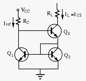
Again, here transistor can be considered as a current-voltage
converter by which the current  through is converted to
the base voltage shared by both and . The following
negative feedback hold the load current
through is converted to
the base voltage shared by both and . The following
negative feedback hold the load current
 constant:
 |
(134) |
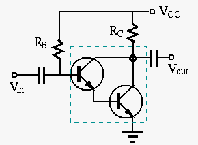
Darlington transistor (Darlington pair) is a compound
structure composed of two transistors, of which the emitter
current of the first transistor becomes the base current of
of the second transistor. The main advantage of the Darlington
transistor is its high current gain
 , which
can be found by the following steps:
, which
can be found by the following steps:
 |
 |
 |
|
 |
|
 |
|
 |
|
 |
|
 |
|
 |
|
 |
|
 |
 .
.
By properly settng the DC operating point of the transistor circuit, it can be working in any one of the following modes:
 ). The DC operating point is
in the middle of the linear range of the transistor to minimize distortion
(clipping). However, the DC power consumption is maximized even the AC
sinusoidal signal is zero.
). The DC operating point is
in the middle of the linear range of the transistor to minimize distortion
(clipping). However, the DC power consumption is maximized even the AC
sinusoidal signal is zero.
 ),
while it is turned off and consumes no energy for the other half.
),
while it is turned off and consumes no energy for the other half.
 )
)
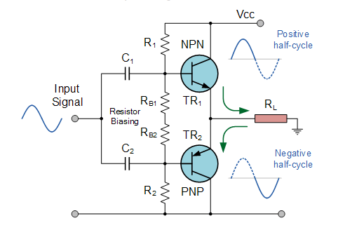
This circuit can be considered as a class AB amplifier that is
typically used as the last stage of an amplification system, such as
in an op-amp circuit, for power amplification with large current and
low output resistance to drive a heavy load (small ). A push-pull
circuit is composed of a pair of two transistors that work in alternation
during the two half cycles of the sinusoidal signal. The circuit can be
implemented in either of the following two ways:
, while PNP transistor is cutoff; during the negative half cycle,
the PNP NPN transistor is conductive and draws current from the load
, while NPN transistor is cutoff. In either polarity, the output
resistance, the conducting transistor, is small.
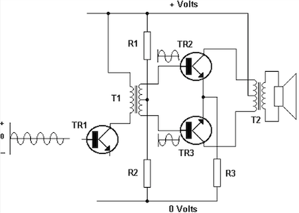
 out of phase (e.g., from a transformer, or from the collector and emitter
of the transistor in previous stage). The transistor receiving positive
peak of the input is active and drives current through , with small
output resistance, while the other transistor receiving negative peak
is cutoff (open-circuit). During the next half cycle, the two transistor
switch roles with the conducting transistor drawing current from the load.
out of phase (e.g., from a transformer, or from the collector and emitter
of the transistor in previous stage). The transistor receiving positive
peak of the input is active and drives current through , with small
output resistance, while the other transistor receiving negative peak
is cutoff (open-circuit). During the next half cycle, the two transistor
switch roles with the conducting transistor drawing current from the load.
 ,
,
 , and the power consumption is
 ,
even when the AC signal is zero.
,
even when the AC signal is zero.
An oscillator is a circuit that receives no input but generates a sinusoidal
output at a desired frequency. A typical oscillator circuit is based on an
active component (a transistor or an op-amp) with positive feedback and an
LC circuit (tank circuit). Initially trigged by switching on the circuit,
the LC circuit starts to resonate at frequency
 , and
the active component with positive feedback compensates for the attenuation
due to the inevitable resistance in the circuit and keeps the oscillation
going.
, and
the active component with positive feedback compensates for the attenuation
due to the inevitable resistance in the circuit and keeps the oscillation
going.
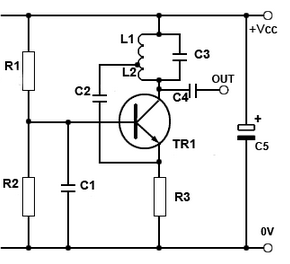
Specifically, the Hartley and Colpitts oscillators are two typical oscillation
circuits. In either cases, a transistor amplifier is used to receive positive
feedback taken from the LC circuit as a collector impedance  , which is
maximized at the resonant frequency, thereby the voltage gain of this circuit
is also maximized. A fraction of the sinusoidal at the collector is positively
fed back to the emitter to prevent attenuation.
, which is
maximized at the resonant frequency, thereby the voltage gain of this circuit
is also maximized. A fraction of the sinusoidal at the collector is positively
fed back to the emitter to prevent attenuation.
 and
and  in series. The resonant frequency is
 .
.
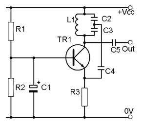
 and
and  in series. The resonant frequency is
 .
.

 |
(135) |
 |
(136) |
When a transistor is used for amplification, its DC operating point of a type A amplifier is typically set in the middle of the load line to maximize the linear dynamic range and thereby minimize the signal distortion (by avoiding the nonlinear region of the transistor circuit).
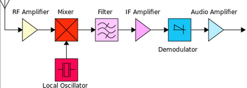
However, in some applications, the nonlinear behavior of the transistor
circuit is taken advantage of, such as in a frequency mixer, used
for converting all radio frequencies
 of different radio/TV
broaccast channels to an intermediate frequency
of different radio/TV
broaccast channels to an intermediate frequency
 , so
that the amplification circuit of the receiver can be specialized for
this intermediate frequency, instead of a wide range of all possible
broadcast frequencies. In radio reception,
, so
that the amplification circuit of the receiver can be specialized for
this intermediate frequency, instead of a wide range of all possible
broadcast frequencies. In radio reception,
 KHz for AM
(535-1605 KHz) and
KHz for AM
(535-1605 KHz) and
 MHz for FM (88-108 MHz). This method
is called the
super-heterodyne reception
which is widely used in all modern radio and TV broadcasting.
MHz for FM (88-108 MHz). This method
is called the
super-heterodyne reception
which is widely used in all modern radio and TV broadcasting.
The output current  of the transistor in a frequency mixer
is approximately an exponential function of the input voltage
of the transistor in a frequency mixer
is approximately an exponential function of the input voltage 
 |
(137) |
 i.e. i.e. |
(138) |
 contains
two frequency components, then the output current can be approximated as:
contains
two frequency components, then the output current can be approximated as:
 |
 |
 |
|
 |
 |
||
|
 |
(139) |
 |
(140) |
 contains many new frequency components in addition
to the two original frequencies
contains many new frequency components in addition
to the two original frequencies  and
and  , including
 ,
,
 ,
,  , and
, and  .
This transistor circuit is therefore called a frequency mixer. By properly
filtering in the circuit following this mixer, one of such frequencies,
such as the difference frequency
(the “beat frequency”)
is amplified, while all other frequency components are suppressed.
.
This transistor circuit is therefore called a frequency mixer. By properly
filtering in the circuit following this mixer, one of such frequencies,
such as the difference frequency
(the “beat frequency”)
is amplified, while all other frequency components are suppressed.
Note that the specific nonlinear behavior of the circuit is not important, as the Taylor series expansion of any nonlinear function will contain constant, first and second order terms as the exponential function assumed above, and the same frequency components will result.
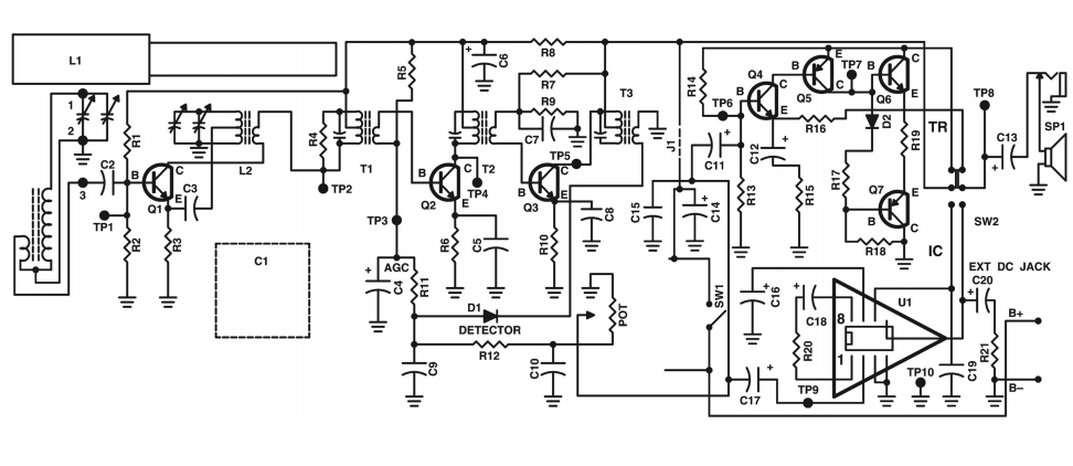
The circuit diagram of a simple super-heterodyne radio receiver is shown below.
Note that the first transistor is an oscillator that also receives signal from
the LC tuning circuit at the base, i.e., it is also a mixer that mixes two
frequencies. The next two transistors amplify frequency component the signal
from the mixer. Here the frequency
 of the local oscillator is
determined by a variablecapacitor, which is adjusted jointly with the capacitor
of the tuning circuit, so that the
of the local oscillator changes
with the carrier frequency
(radio frequency) of the broadcast signal
received by the antenna so that their difference, the intermediate frequency, is
always a the same:
of the local oscillator is
determined by a variablecapacitor, which is adjusted jointly with the capacitor
of the tuning circuit, so that the
of the local oscillator changes
with the carrier frequency
(radio frequency) of the broadcast signal
received by the antenna so that their difference, the intermediate frequency, is
always a the same:
 |
(141) |