Next: Analysis of Op-Amp Circuits Up: Chapter 5: Operational Amplifiers Previous: Chapter 5: Operational Amplifiers
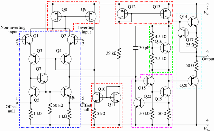
The circuit schematic of the typical 741 op-amp is shown below:

A component-level diagram of the common 741 op-amp. Dotted lines outline:
Like all op-amps, the circuit basically consists of three stages:
 .
.
 of both polarities
(typically
  V).
V).
Although the op-amp circuit may look complicated, the analysis of its operation and behaviors can be simplfied based on the following assumptions:
 can be treated as infinity
 .
.
 ),
and could be approximated to be zero
  .
.
 can be treated as zero
 ,
i.e., the output
  is not affected by the load
  (so long as it is
much greater than
  ).
).
 ), i.e., the property of the op-amp
remain unchanged for all frequencies of interest.
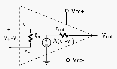
Based on these approximations, an op-amp can be modeled in terms of the following three parameters:

 : very large, typically a few mega-Ohms or
higher (
 , e.g., 741
 ), depending on
the frequency and specific components used (e.g., BJT or FET).
 :, very small, typically a few tens of
ohms, e.g., 75
  .
.
 :, based on both the inverting input
  and the non-inverting input
  :
:
 |
(1) |
 is the differential-mode gain and
  is the common-mode gain.
It is desired that
 and
and
 , i.e., the
output is only proportional to the difference
  between the two inputs.
The common-mode rejection ratio (CMRR) is defined as the ratio between
differential-mode gain and common-mode gain:
 |
(2) |
Also, as the output


As 


 , output impedance
 and voltage gain
  , as shown in (B). Then the voltage follower
can be modeled by its input impedance
  , output impedance
  ,
and voltage gain
  , as shown in (C).

Specifically, 


 : Applying KVL to the loop we get
 |
(3) |
 we get the input impedance:
 |
(4) |
 : The open-circuit output
voltage is
 |
(5) |
 |
(6) |
 and
and  . We therefore have
 |
(7) |
 :
With a short-circuit load, we have
 , and the
short-circuit current can be found by superposition:
 |
(8) |
 , we get the output impedance
(Thevenin's model):
 |
(9) |

In summary, we see that the voltage follower has a unit voltage gain, but
much increased input resistance


Example:

The figure on the left shows a circuit represented by an ideal voltage
source 


 |
(10) |
 is only a fraction
of the voltage due to the voltage drop
 across the
internal resistance
  . If it is desired for the output voltage to
be as close to the source as possible, the internal resistance
  needs to be small compared to the load resistance
  .
.
Next consider inserting a voltage follower (buffer), in between the
source and the load, as shown in the middle figure. The follower is
modeled by its input and output resistances 


 |
(11) |
 can be very close to
source voltage, i.e.,
 , due to the nature of the
op-amp:


As the analysis of the circuit using full model of the op-amp is very involved, certain approximation is made to simplify the analysis.
 :
:
As


 |
(12) |
 we get
 |
(13) |
![$\displaystyle v_{out}=v_s-(R_1+R_f) i_{in}
=v_s\left[1-\frac{(A+1)(R_1+R_f)}{(A+1)R_1+R_f}\right]
=v_s\frac{-AR_f}{(A+1)R_1+R_f}$](img75.svg) |
(14) |
 |
(15) |
 .
.
We assume 


 |
(16) |
 :
:
 |
(17) |
 |
 |
![$\displaystyle \frac{v_s-v^-}{R_1}
=\frac{v_s}{R_1}\left[1-\frac{R_f}{R_f+(A+1)R_1}\right]$](img83.svg) |
|
 |
 |
(18) |
 by
by  we get
 |
(19) |
 !
!
 to simplify the analysis.
 |
(20) |
 , the above becomes
 |
(21) |
 we get
 |
(22) |
 we get
 |
(23) |
 |
 |
![$\displaystyle [v^--(-Av^-)]\frac{r_{out}}{R_f+r_{out}}-Av^-
=v^- \left(\frac{r_{out}-AR_f}{R_f+r_{out}}\right)$](img92.svg) |
|
 |
 |
(24) |
 |
 |
 |
|
 |
 |
(25) |
 and
and
 .
.
In summary,
 |
(26) |
 |
(27) |
 |
(28) |

The three parameters of this non-inverting amplifier can be found to be (see here):
 |
(29) |
 |
(30) |
 |
(31) |
 is a little better, but both
  and
and  are
a little worse. In particular if
  , this non-inverting amplifier
becomes a voltage follower with
 ,
,
 ,
and
,
and
 .
.