Next: Energy Sources Up: Chapter 1: Basic Quantities Previous: Examples: Mechanical and Electrical
Here are some terminologies for electric circuits:
In a circuit diagram, both the direction of a current through, and the polarity of a voltage across an element can be arbitrarily labeled. The actual direction and polarity will be determined by the sign of the specific values obtained after the circuit is solved. For example, a current labeled in the left-to-right direction with a negative value is actually flowing in the right-to-left direction.
Kirchhoff's Laws
The algebraic sum of the currents into a node is zero:
 |
(70) |
Here we can assume the directions of all currents through the elements are either into or out of the node.
The algebraic sum of all voltage drops around a loop is zero:
 |
(71) |
Here we can assume the polarities of all voltages across the elements are from high (+) to low (-), while going around the loop in either clockwise or counter-clockwise direction.
Example 1:
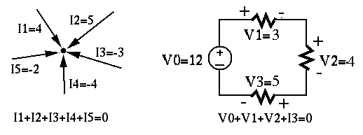
Assume currents flowing into the node are positive and those leaving the
node negative, the KCL states:
 .
.
Assume the current flows around the loop in clockwise direction, the KVL
states:
 .
.
Example 2: Given the circuit below, find  ,
,  ,
,  ,
,  and
and  .
.
According to Ohm's law, we have
 .
.
Apply KVL to the loop on the right to get:
 |
(72) |
According to Ohm's law, we have
 .
.
Apply KCL to the middle node on top to get:
 |
(73) |
Again by Ohm's law, we get
 .
.
Apply KVL to the loop on the left to get:
 |
(74) |
The series and parallel combinations of circuit components
According to KVL, the sum of voltages across
the resistors is equal to the input voltage:
 |
 |
 |
|
|
 |
(75) |
 |
(76) |
 |
(77) |
According to Ohm's law, the voltage  across the kth resistor
  can be
found to be:
can be
found to be:
 |
(78) |
 , we have
 |
(79) |
According to KCL, the sum of currents through the resistors is equal to
the input current:
 |
|
 |
|
|
 |
(80) |
 |
(81) |
 |
(82) |
In particular, when ,
 |
(83) |
According to Ohm's law, the current  through the kth resistor can be
found to be:
through the kth resistor can be
found to be:
 |
(84) |
, we have
 |
(85) |
 |
(86) |
 |
(87) |
 |
(88) |
 |
(89) |
 |
(90) |
 |
(91) |
 |
(92) |
 |
(93) |
 |
(94) |
| Resistor R | Inductor L | Capacitor C | |
| Governing Equation |  , ,  |
 , ,
 |
 , ,
 |
| Series connection |
 , ,
 |
 |
 |
| Parallel connection |
 , ,
 |
 |
 |
Example 3 Consider the following six circuits as either current or voltage dividers.
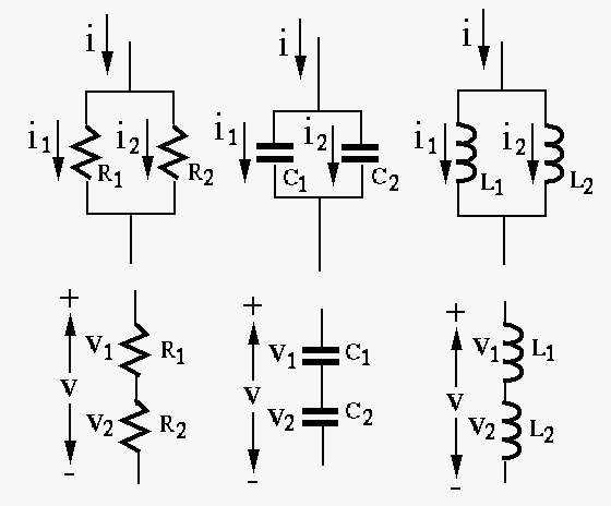
 and
and  in
terms of the given current
in
terms of the given current  and the resistances, capacitances, or
inductances.
and the resistances, capacitances, or
inductances.
 |
(95) |
 |
(96) |
 |
(97) |
 and
and  in
terms of the given voltage
in
terms of the given voltage  and the resistances, capacitances, or
inductances.
and the resistances, capacitances, or
inductances.
 |
(98) |
 |
(99) |
 |
(100) |