
Lab 1 Build a Gamepad Controller

Deliverables
- Basic: Controller with 2 joysticks, 4 buttons, and 1 switch
- Extra: Additional buttons, mode changing switch(es), creative use of sensors, justification for design/layout choices.
Introduction
Video games have access to vast computational power in this day and age, but to what end? What good is all that power if we cannot better interact or interface with the video game? The user experience is an integral part of any gaming experience, and the pursuit of a more intuitive and fluid controller continues to this day. You will be delving into this process in the first two labs.
Principles of controller use and design
The most important role of the controller is to convert the player's physical inputs (typically finger motions, but may include larger bodily motions or vocalizations) into electrical signals that are then in turn translated into something the game can understand. This is accomplished with sensors. A physical event - the pressing of a button, the rotation of a gyroscope, the turning of a potentiometer - creates a change in the electrical signals monitored by a microprocessor onboard the controller. The microprocessor, in our case an Arduino, parses this data and sends the pertinent information to the PC or game console.
Secondary of the controller's roles is to provide feedback to the player. Based on in-game events, the game may send electrical signals to the controller, which then activates the appropriate actuator. Using solenoids or vibration motors, the controller sends a physical haptic-feedback signal to the player, adding to their sensory experience of the game and their immersion therein.
Qualities of Good Design
What makes a good controller? When optimized properly, a good controller can diminish and even eliminate the physical and emotional barriers between human user and the game. That definition lends itself to a number of metrics:
A good controller has an appealing form. To prevent strain or fatigue on the player's hands, the controller should be ergonomic. It should sit nicely in the hands, fitting to contours. It should be neither too light nor too heavy; it should be solid but not unwieldy. Buttons and joysticks should have a pleasant and comfortable actuation and be within reach of the player's fingers. There should be no sharp edges or points. And lastly, a good controller should be aesthetically pleasing. It should have a sleek and solid appearance and a consistent color scheme.
Physical Construction
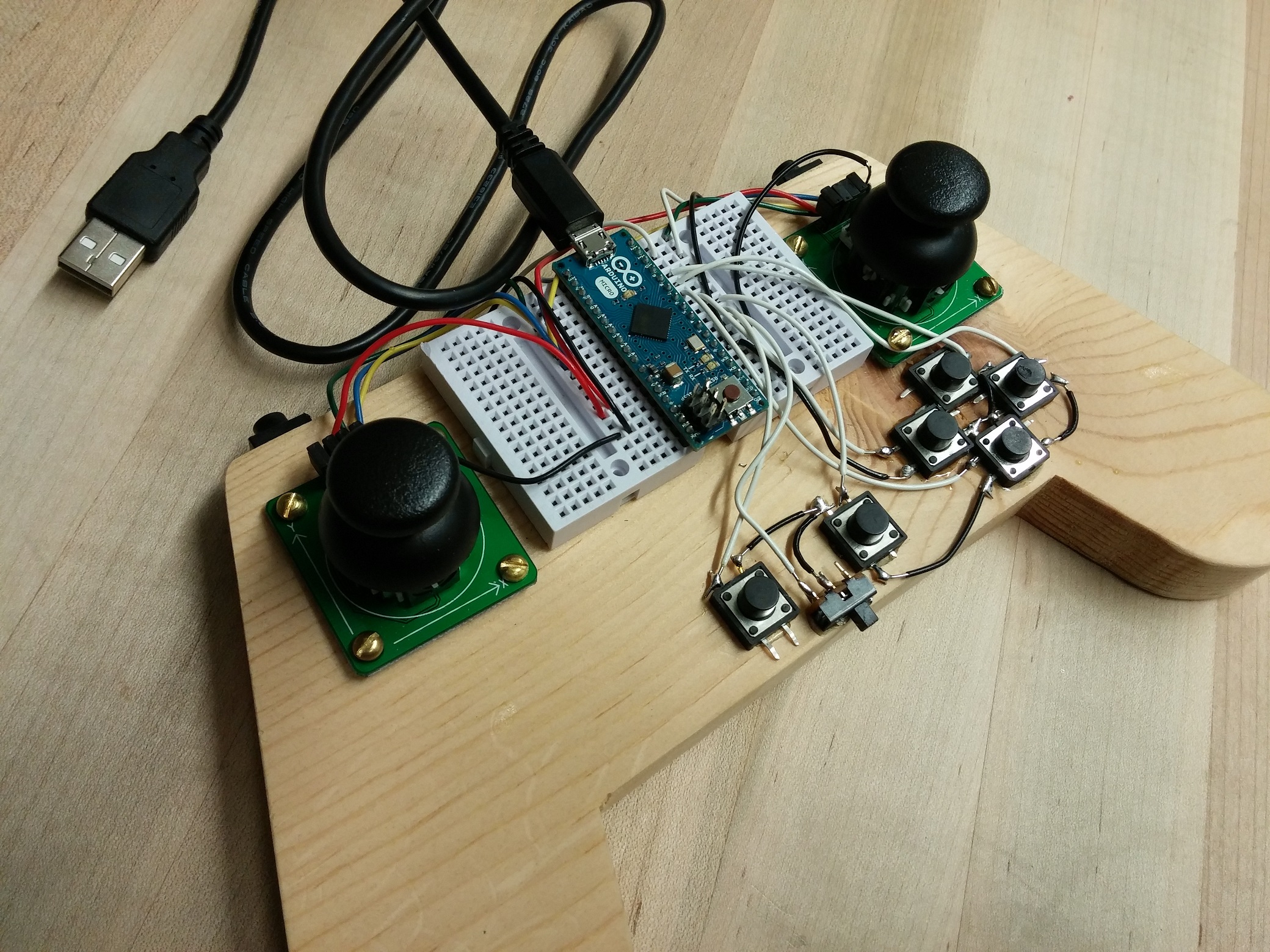
For this first lab, you will be putting together the hardware for your controller; the software side will be covered in lab 2. As a start, we have provided a simple plywood base for mounting components to, and some ideas for ways that the components can be arranged and attached. The specifics, though, are up to you. Feel free to customize the controller shape, the button quantity and arrangement, and the various types of inputs. Remember though, that you will be using these controllers to play OpenArena (an open-source FPS based on Quake III), so make sure you have enough buttons and joysticks to handle this! Look up the inputs you'll need to have available, take inspiration from comercially-produced controllers, and make whatever you think will work best for you.
Basic Controller Template, and Construction!
The controller baseboard we've provided is simple and rough. Quite literally, in fact; you'll want to sand down the edges at the very least to make the controller more comfortable to hold and less prone to splinters (we've provided sandpaper for this purpose). If you want, you can even sand it down to a smoothly contoured shape. We designed the baseboards to fit all the buttons, joysticks, and hardware you should need. If, however, you would like to customize the shape or even the material of your controller - making a split system like the Nintendo Wiimote-Nunchuck system or using metal/acrylic, for example - the Solidworks starter file can be downloaded here.
If you would simply like a new custom wooden baseboard, you can ask us or the professor for stock plywood. Then if you are machine shop certified, you can utilize the Makerbot in the student woodshop to cut out your new shape as designed from the CAD file. If you choose to take this route, remember to export your solidworks file as a DXF vector graphic! There are instructions on ShopBot operation by the computer in the woodshop, and shop proctors will be more than happy to help!
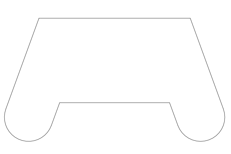
Here is the default shape of the wooden baseboard controller that you have been provided.
Using the default baseboard as given, we've provided the following suggested build layout to guide you on your quest to piece together your controller! Notice the left and right triggers need extra small wooden wedges wood glued to the backside of the controller to be properly mounted in this configuration.
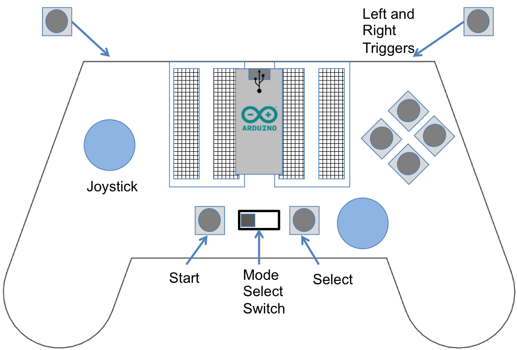
This is only a suggestion of a handheld controller layout, with more than enough buttons and controls. This layout is meant to fully engage with a first person shooter game. Make sure you thoroughly test the physical usability of your controller! Ergonomics do matter. Make sure repeated button presses and placements feel natural to you. The example we've given is just a loose suggestion. Its up to you to determine the details of final placement of components and controller shape!
From here on out, build instructions will be operating under the assumption you are attempting a layout similar to the example.
Basic Electronics, Soldering, Etc.
Feeling overwhelmed with soldering, basic electronics, and hardware? Read our quick guides at this link.
Breadboards
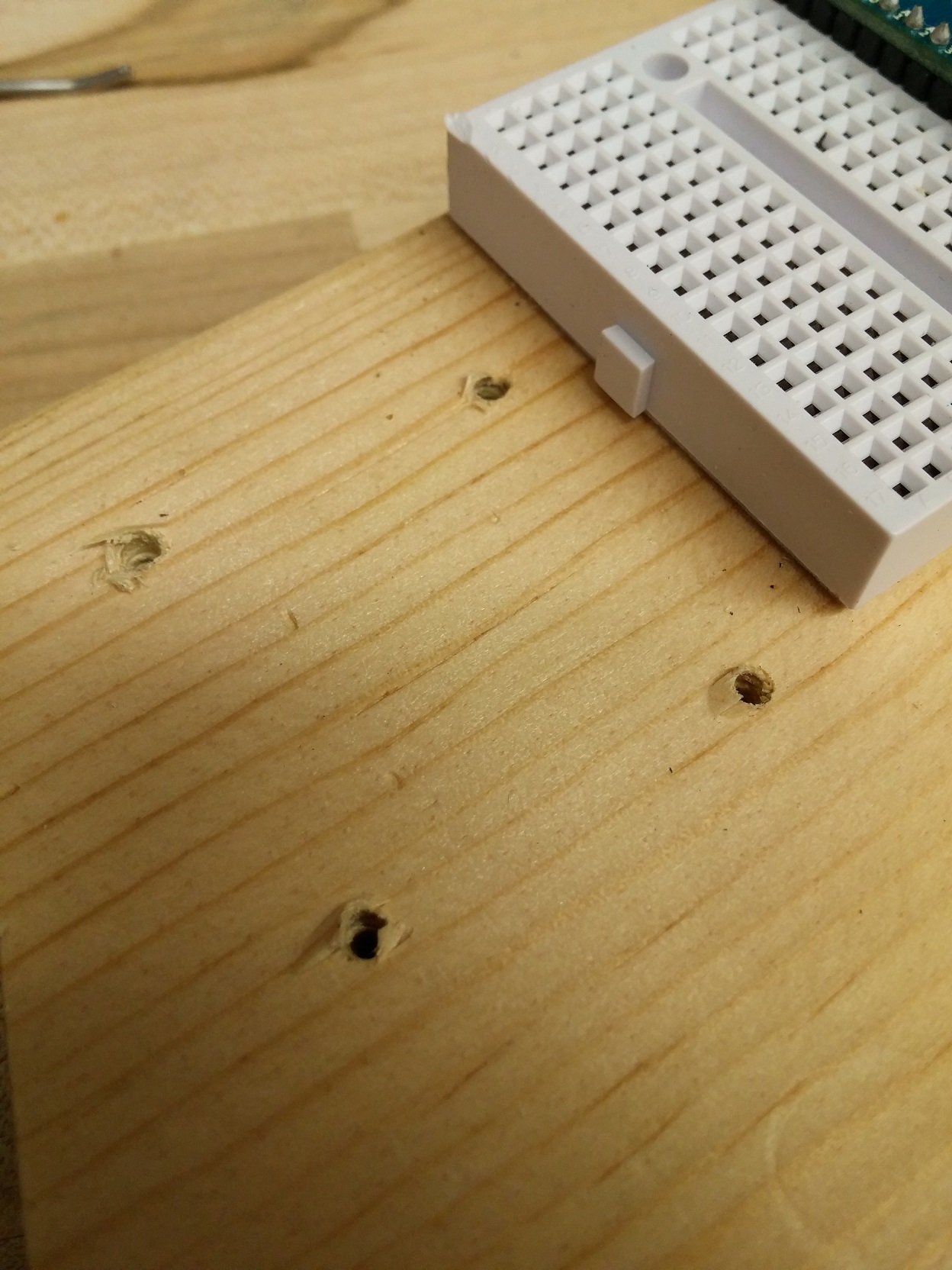
Each breadboard has 17 double-rows of five holes. Each of these sets of five is electrically connected, with a separation in the middle so that DIP (Dual In-Line Package) components can be inserted without shorting each pair of pins together.
Attach the pair of small breadboards to the surface of the controller for ease of prototyping. For a quick and simple attachment, feel free to use the adhesive backing on the breadboards. If you need something more secure, or need to remove and relocate a breadboard, you're better off using screws through the two mounting holes to attach it. Once your breadboards are secure, insert the provided Arduino Micro's headers as shown in the recommended layout image.
Joysticks
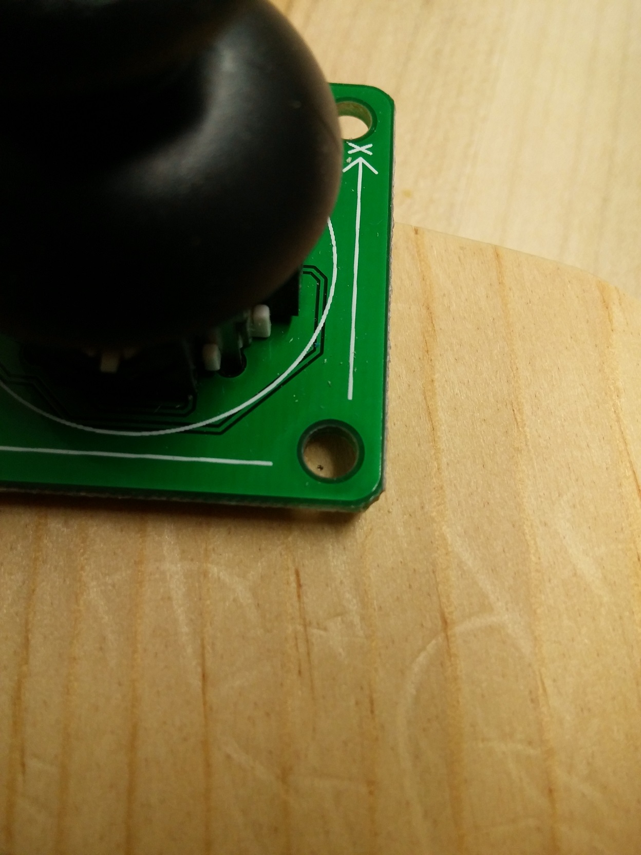
To provide analog motion input to your controller for character and camera movement, you will be using a pair of analog joysticks. Each joystick is actually a pair of 5 kilo-ohm potentiometers mounted orthogonally to give X and Y deflection. Each potentiometer acts as a voltage divider whose ratio is dependent upon the user's deflection of the joystick. By providing 5V power to the "+" voltage pin of the joystick and grounding the output, those two dividers each give an analog voltage on the x and y output pins corresponding to the joystick's position.
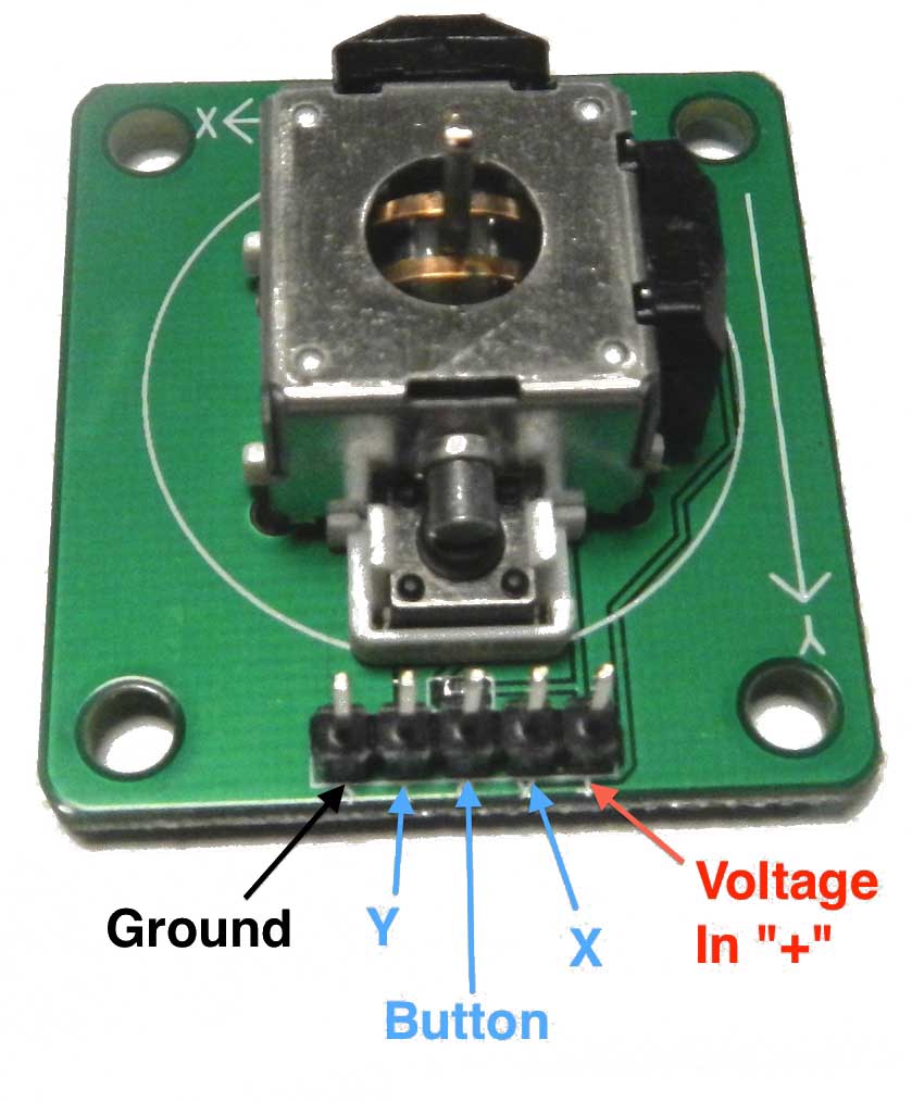
Each provided joystick also has a small tactile switch that provides a click-in functionality. When the switch is actuated, a corresponding pin on the joystick breakout board is pulled high. It's up to you if you want to take advantage of this feature.
To mount your joysticks, we recommend using the provided wood screws. Place your joystick where you want it, taking care to keep the x and y axes aligned as necessary. Use a pencil or pen to mark where the four mounting holes are. Drill a pilot hole in each location to make inserting the screws easier, then use them to secure the breakout board to the wood.
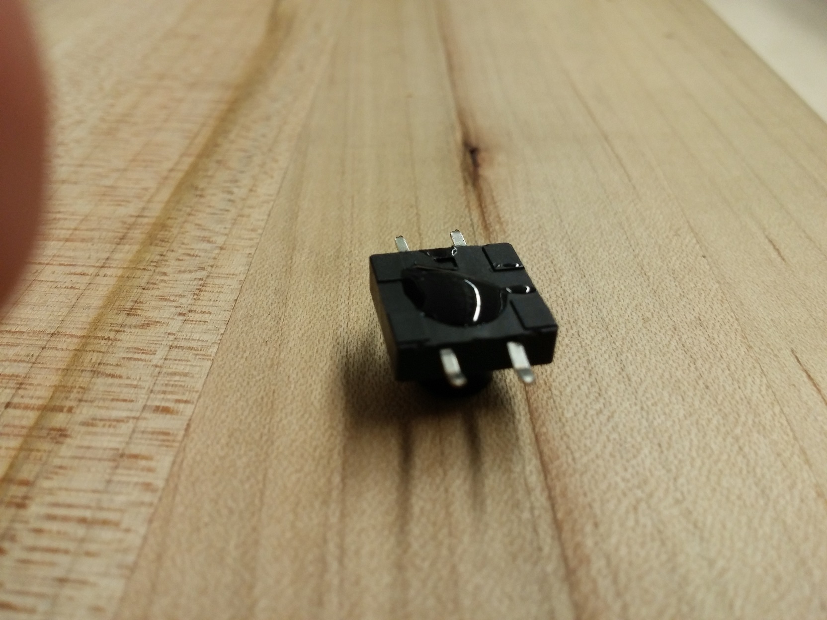
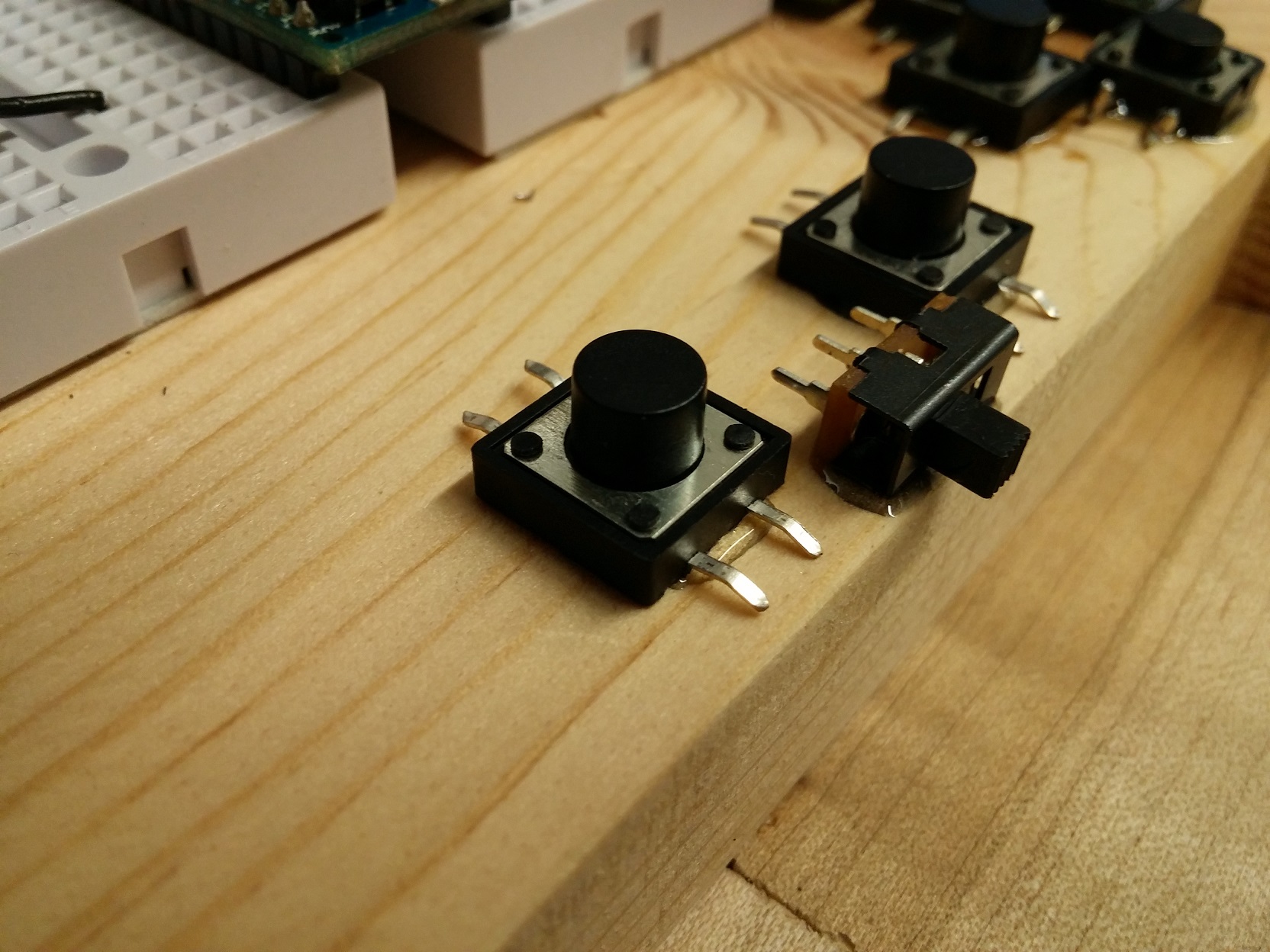
Tactile Switches
Each tactile switch has four leads in two pairs. Each pair is internally connected, regardless of switch position. When the button is pressed, the switch between the pairs is closed and all four pins become electrically connected. However, this switch cannot simply be used by connecting one side to a digital input and the other to either ground or 5V; When pressed, the switch will be pulled to a certain voltage, but when unpressed the voltage will be free to float and may cause your code to register unwanted inputs. You should use either a pull-up or pull-down resistor. For more information on using these, see the skills manual.
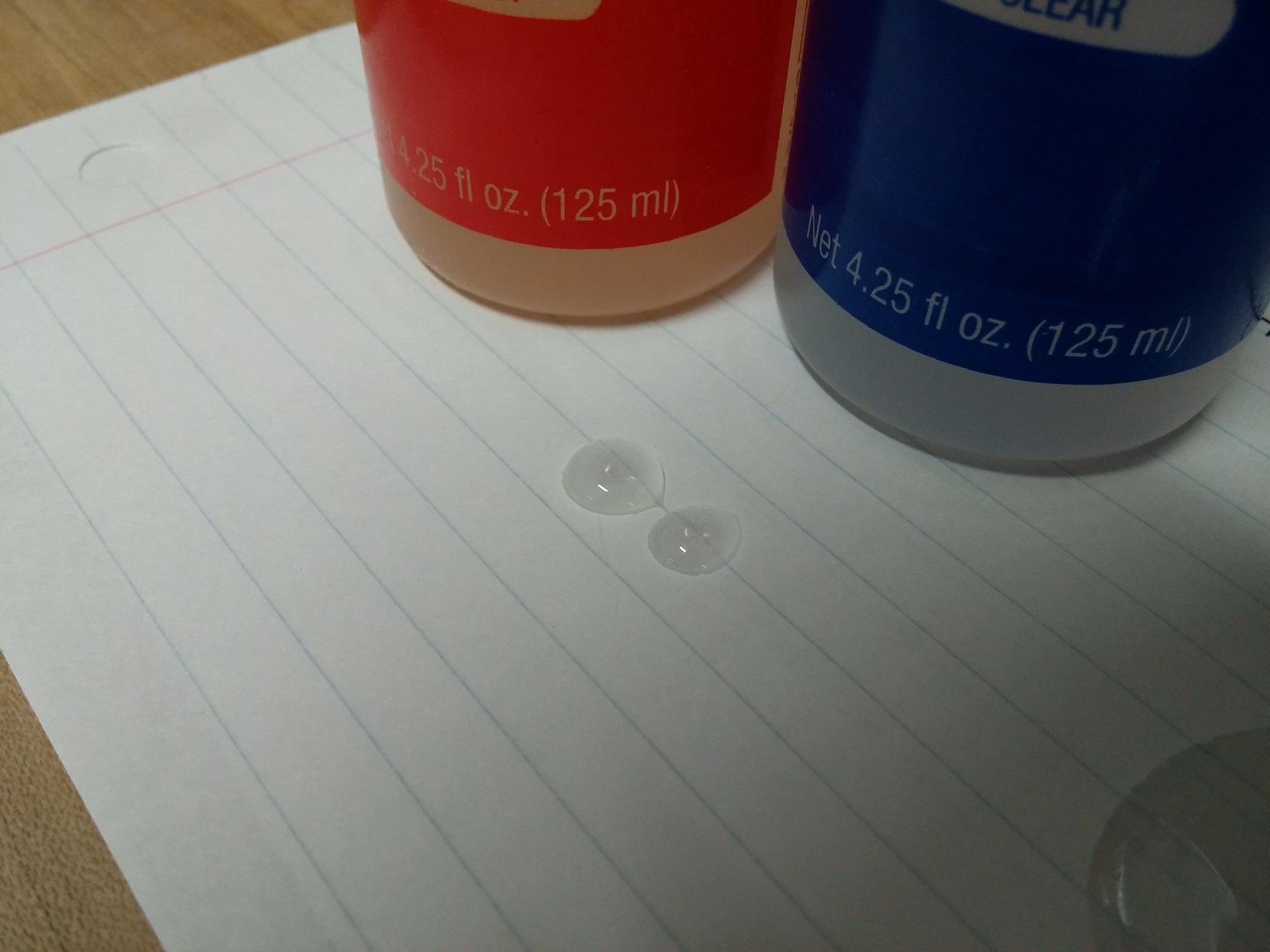
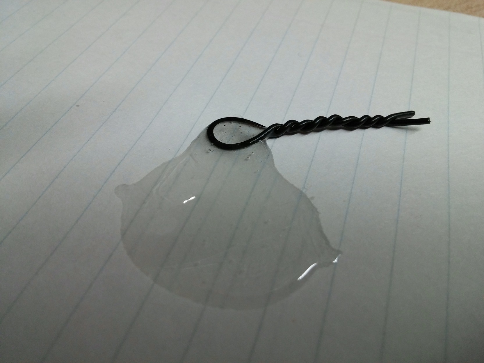
To attach the switches, just use a bit of epoxy:
Electrical Connections
You should use the provided male-to-female jumper wires to connect the joystick breakout pins to the breadboard
Solder solid-core wire to the buttons and switches to connect them to the breadboard. Don't forget to use pull-up or pull-down resistors.
Testing your Controller
For this lab, you should just test that all of your electrical connections are good. This can be done using a multi-meter. Your digital inputs (switches and buttons) should show a single, steady voltage (0 or 5V) when pressed, and the other when unpressed. Your analog input pins (x and y inputs from the joysticks) should show a steady voltage directly related to joystick position.
What to turn in and how
Write up a blog like status report to the course website following the directions here:
Advanced HID (Human Interface Device)
There's a nice HID library that brings some more features to the arduino micro. This could be used to do absolute mouse positioning and USB gamepad controls.
Completed lab reports
Materials
This lab requires a set of materials that students in the class can get from the Engineering stock room in a kit. Here is a list of the materials provided with links for possible vendors for anyone who wants to build their own:
| Part | Quantity | Vendor link |
|---|---|---|
| Arduino Micro | 1 | Adafruit |
| Tactile Switches | 10 | Sparkfun |
| Joystick Potentiometer with Breakout Board | 2 | RobotShop |
| Switch | 1 | Digikey |
| Hardwood Board | 1 | Lowes |
| Arduino Mini-breadboard | 2 | Mini In The Box |
You will also need a spool of wire and soldering equipment to connect the switches and buttons. In addition, the following is useful for connecting the joystick potentiometers.
| Part | Quantity | Vendor Link |
|---|---|---|
| Female to Male Header Pack | 1 | Adafruit |
Some alternate supplier options that may work but I have not tested:
| Part | Price | Vendor Link |
|---|---|---|
| 1 Piece Joystick w/ breakout | $1.66 | Banggood |
| 5 Piece Joystick w/ breakout | $4.99 | Banggood |
| 10 Piece Joystick w/ breakout | $9.29 | Banggood |
| 20 Piece Joystick w/ breakout | $16.99 | Banggood |
| Arduino Micro w/ USB cable | $9.50 | Banggood |
| 40 piece female to male cables | $2.10 | Banggood |
| 5 piece 170-hole mini breadboards | $5.68 | Banggood |
| 10 piece 170-hole mini breadboards | $10.20 | Banggood |
This lab was developed by Kirklann Lau and Richard Piersall.