Next: Multi-stage Amplification Up: ch4 Previous: AC equivalent circuits
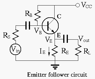
The input and output of an emitter follower are the base and the emitter, respectively, and the collector is at AC zero. The circuit is therefore a common-collector circuit (for AC).
The negative feedback effect due to  can be shown qualitatively:
 |
(110) |
 |
(111) |
 we get:
 |
(112) |
 |
(113) |
 |
(114) |
Example 1
 ,
,
 ,
,
 ,
,  , then
 |
 |
 |
|
 |
|
 |
|
 |
|
 |
|
 |
(115) |
Example 2
In the same circuit, find so that the DC operating
point is in the middle of the linear region, i.e.,
 . For this to be the case,
we need
. For this to be the case,
we need  :
:
 |
(116) |
we get
 .
We can further verify this result:
.
We can further verify this result:
 |
(117) |
 |
(118) |
AC small-signal equivalent circuit
Based on small signal model of the transistor:
we find the AC equivalent circit of the emitter follower:
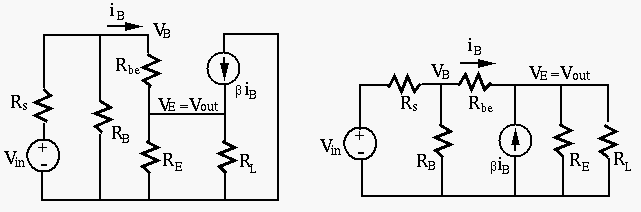
and we can further find the three system parameters: voltage gain, input resistance, and output resistance, as shown below.
As  is significantly greater than
  and
and  , it is
neglected in the analysis below.
, it is
neglected in the analysis below.
 |
(119) |
 |
(120) |
 .
.
We note that the voltage gain  is smaller than but
approximately equal to 1. Note that is positive, i.e.,
the output voltage is in phase with the input voltage.
is smaller than but
approximately equal to 1. Note that is positive, i.e.,
the output voltage is in phase with the input voltage.
The input resistance is the parallel combination of and
 , the resistance of the circuit to right of the base
of the transistor, including the load
, the resistance of the circuit to right of the base
of the transistor, including the load  , which can be found
as the ratio of
, which can be found
as the ratio of  and
and  . We first get:
![$\displaystyle v_b=i_b r_{be}+v_{out}=i_b\, [ r_{be}+(\beta+1)(R_E\vert\vert R_L) ]$](img482.svg) |
(121) |
 |
(122) |
 |
(123) |
 , we see that the
emitter follower has much higher input resistance.
, we see that the
emitter follower has much higher input resistance.
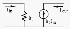
The output resistance is the parallel combination of and
 , the resistance of the circuit to the left of the
emitter of the transistor (including
, the resistance of the circuit to the left of the
emitter of the transistor (including  ), which can be
found as the ratio of the open-circuit voltage
), which can be
found as the ratio of the open-circuit voltage  and the short-circuit current
  .
.
(
 ):
):
Due to the unity gain of the voltage gain follower,
is approximately the same as the source voltage
 .
.
( ):
):
 |
(124) |
 |
(125) |
 |
(126) |
 , we see that the emitter follower has much
lower output resistance.
, we see that the emitter follower has much
lower output resistance.
Conclusion:
The emitter follower is a circuit with strong negative feedback,
i.e., the full output
 is fed back to become part of
its input
is fed back to become part of
its input  . Due to this deep negative feedback, it has the
following properties:
. Due to this deep negative feedback, it has the
following properties:
 .
.
 (assuming
open-circuit with
).
(assuming
open-circuit with
).
 (assuming ideal source with
  ).
).
 and
, we have
and
, we have
 and
and
 . The emitter follower acts as an impedance
transformer with a ratio of
. The emitter follower acts as an impedance
transformer with a ratio of  .
.
Although the emitter follower circuit does not amplify the signal
voltage, it drastically improves the input and output resistances,
when compared with the common-emitter circuit with
 and output resistances
.
and output resistances
.
Due to its high input resistance  , it draws little current
from the source, causing little internal voltage drop across the
internal resistance of the source, also due to its low output
resistance
, it draws little current
from the source, causing little internal voltage drop across the
internal resistance of the source, also due to its low output
resistance  , it can drive heavy load (low ) without
lowering its output voltage. It is therefore widely used as a
buffer between two stages of a multi-stage amplification circuit.
, it can drive heavy load (low ) without
lowering its output voltage. It is therefore widely used as a
buffer between two stages of a multi-stage amplification circuit.
Example
For the emiter follower in the example above, the input resistance
is approximately
 , and
the output resistance is approximately
.
, and
the output resistance is approximately
.