Next: Summary Up: Chapter 3: AC Circuit Previous: Real and Reactive Power
Maximize power delivery in AC systems
Previously we considered the maximization of the power received by a
resistive load 


 |
(411) |
 |
(412) |
 |
(413) |
 , which is minimized if the imaginary part
 is zero, i.e.,
  (while the real part
  is
always positive). Now
  becomes:
 |
(414) |
 , which is maximized
if it matches the internal resistance of the source
  , as discussed
before. Combining these two requirements
  and
and  , we conclude
that if
 , i.e., the load impedance
  is the
complex conjugate of the internal impedance
  , the load receives maximum
power:
 |
(415) |
Example 1:
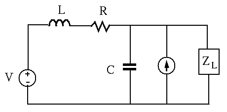
Find load impedance 


Assume voltage source 


 : turn off both voltage and current sources, find
 and the internal (Thevenin or Norton) impedance:
 |
(416) |
 ,
,
 .
.
 across load port
by superposition principle. Due to voltage source alone:
 |
(417) |
 |
(418) |
 |
(419) |
 through load port
by superposition principle:
 |
(420) |
 |
(421) |
 |
(422) |
 |
(423) |
 |
(424) |
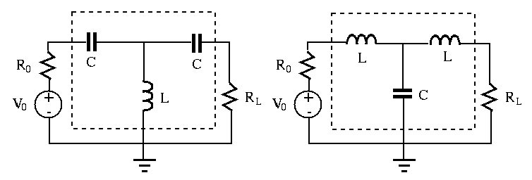
Geometric mean method
The load resistance 


The matching circuit is composed of two capacitors 


The total impedance of the new load composed of all four components 


 |
(425) |
 |
(426) |
 to match the internal resistance
  of the
source, we have
 i.e. i.e. |
(427) |
 is the geometric mean of the source and load resistances
 and
and  . Note that the matching circuit consumes no real power as it
does not have any resistance. We can verify that the power consumed by
  is
is
 .
.
This method can be generalized to any AC circuit composed of a voltage
source with an internal impedance


 of capacitor
  in series with
the source by
  , so that the additional reactance
  cancels the source reactance
  , and the impedance in the source
branch is
  .
.
 of capacitor
  in series with
the load by
  , so that the additional reactance
  cancels the load reactance
  , and the impedance in the load
branch is
  .
.
We can show that the impedance of the equivalent load composed
of 


 |
 |
 |
|
 |
 |
(428) |
As this method requires a fixed reactance 

Example 2:
An audio amplification circuit with an output voltage 


 |
(429) |
 is:
is:
 |
(430) |
 |
(431) |
 of the total power, while the
remaining
 of the power is consumed internally.
To maximize the power delivered to the speaker, we add a matching circuit
composed of 


As the frequency in the system is not constant, the matching is achieved only at one particular frequency, typically chosen to be the middle of the frequency range.
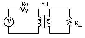
Matching resistances by a transformer
An ideal transformer can be used to match the load 

 i.e. i.e. |
(432) |
 is the turn ratio. As
  and
and  , we
have
 |
(433) |
 , which is related to the real load
by
 . For the load to receive maximum power
  , we
need to match the equivalent load resistance
  to
to  :
:
 i.e. i.e. |
(434) |

Example 3:
In the previous example with


Example 4:


The load resistor receives maximum power if its resistance matches the internal resistance of the voltage source.
 to
to
 on the primary side.
 to
to  , i.e.,

 .
.
 :
:
 |
(435) |
 is the same, due to ideal
transformer.