Next: The Twin-T notch (band-stop)
Up: Chapter 6: Active Filter
Previous: First and Second Order
The
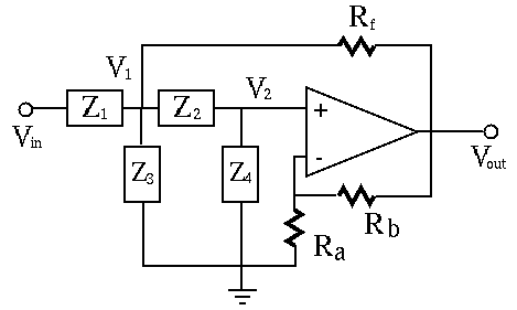
Sallen-Key filters
are second-order active filters (low-pass, high-pass, and band-pass) that
can be easily implemented using the configuration below:
We represent all voltages in phasor form. Due to the virtual ground
assumption,
 at non-inverting input is virtually
the same as that at the inverting input, which is connected to the
output
at non-inverting input is virtually
the same as that at the inverting input, which is connected to the
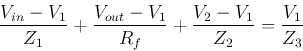
output  . Applying KCL to nodes a and b to get:
and
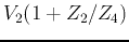
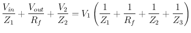
The second equation can also be written as
Substituting these into the first equation we get
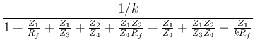
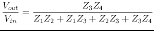
Now the frequency response of the Sallen-Key filter can be found as
the ratio of and  :
:
- Second order low-pass filter
If we let  ,
,  ,
,
 ,
,
 ,
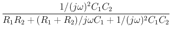
then the FRF becomes:
,
then the FRF becomes:
This is a 2nd-order low-pass filter with
and
As there are only two parameters  and
and  or
or  to satisfy, we can arbitrarily set any two of the four variables
  ,
,
 ,
,  , and
, and  , and then solve for the other two. For example,
for convenience, if we let
, and then solve for the other two. For example,
for convenience, if we let  , we get
- Second order high-pass filter
If we let
 ,
,
 ,
,  ,
,  ,
then the FRF becomes becomes:
,
then the FRF becomes becomes:
This is a 2nd-order high-pass filter with
and
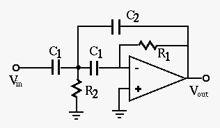
We further consider a band-pass filter shown below:
By voltage divider and virtual ground, we get
Apply KCL to node  to get:
Apply KCL to node  to get:
Rearrange the terms, and replace by
 to get
Further rearrange the terms and replace by  to get
Further rearrange the terms
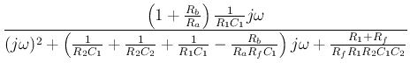
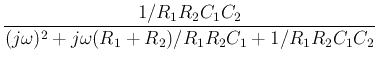
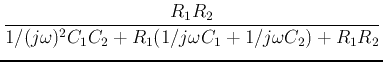
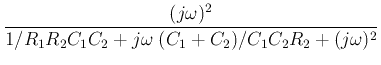
Finally we get the frequency response function:
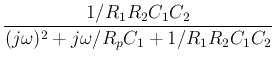
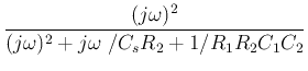
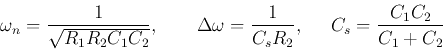
If we let
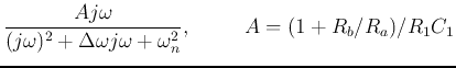
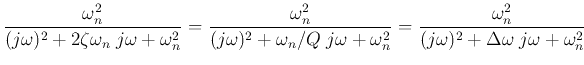
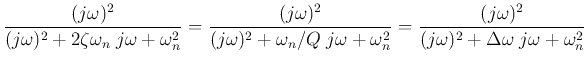
the frequency response function becomes
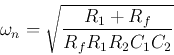
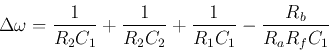
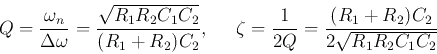
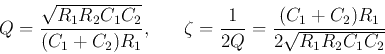
This is a band-pass filter with the peak frequency equal to the natural
frequency:
the bandwidth
The gain of the filter is controlled by  .
.
More Examples of op-amp filters are listed below
(with detailed analysis in here):
Next: The Twin-T notch (band-stop)
Up: Chapter 6: Active Filter
Previous: First and Second Order
Ruye Wang
2019-05-07

![\begin{displaymath}
\frac{V_{in}}{Z_1}+\frac{V_{out}}{R_f}
=kV_{out}\left[\lef...
..._f}
+\frac{1}{Z_2}+\frac{1}{Z_3}\right)-\frac{1}{Z_2}\right]
\end{displaymath}](img110.png)
![$\displaystyle kV_{out}\left[\left(1+\frac{Z_2}{Z_4}\right)
\left(\frac{1}{Z_1}
...
..._f}+\frac{1}{Z_2}+\frac{1}{Z_3}\right)-\frac{1}{Z_2}\right]-\frac{V_{out}}{R_f}$](img112.png)
![$\displaystyle V_{out}\left\{k\left[\left(1+\frac{Z_2}{Z_4}\right)\left(\frac{1}...
...}+\frac{1}{Z_2}+\frac{1}{Z_3}\right)-\frac{1}{Z_2}\right]-\frac{1}{R_f}\right\}$](img113.png)

![$\displaystyle \frac{1}{Z_1\left\{k\left[\left(1+\frac{Z_2}{Z_4}\right)\left(\fr...
...+\frac{1}{Z_2}+\frac{1}{Z_3}\right)-\frac{1}{Z_2}\right]-\frac{1}{R_f}\right\}}$](img115.png)
![$\displaystyle \frac{1/k}{Z_1\left[\left(1+\frac{Z_2}{Z_4}\right)\left(\frac{1}{...
...{R_f}+\frac{1}{Z_2}+\frac{1}{Z_3}\right)-\frac{1}{Z_2}\right]-\frac{Z_1}{kR_f}}$](img116.png)