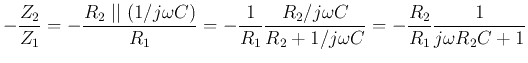
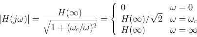
- Low-pass filter:
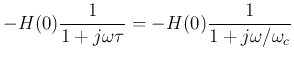
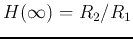
where  is the DC gain when
  ,
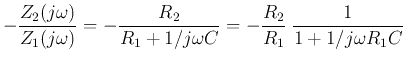
,  ,
,
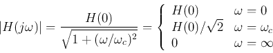
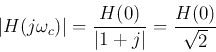
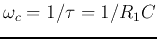
 is cut-off or corner frequency, at which
 . Intuitively, when frequency is high,
 is small and the negative feedback becomes strong,
and the output is low.
is small and the negative feedback becomes strong,
and the output is low.
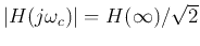
At the cut-off frequency
 , we have
and
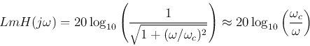
i.e., the log-magnitude of  is approximately
  lower than that of
  .
.
Also, when
 , we have
When frequency is a decade (10 times) higher
i.e., the log-magnitude of
 is approximately 20 dB
lower than that of
is approximately 20 dB
lower than that of  .
.
For example, when  ,
,
 , the
Bode plots
are shown below:
, the
Bode plots
are shown below:
- High-pass filter:
where
 is the gain when
 ,
,
 , and
, and
 is the cut-off or corner
frequency, at which
is the cut-off or corner
frequency, at which
 . Intuitively,
when frequency is low
. Intuitively,
when frequency is low  is large and the signal is difficult
to pass, therefore the output is low.
is large and the signal is difficult
to pass, therefore the output is low.
For example, when  ,
,
 , the Bode plots are shown below:
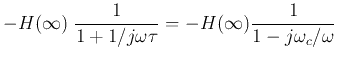
If we let  , i.e.,
  , and ignore the negative sign (
 phase shift), the low-pass and high-pass filters can be represented by their
transfer functions with
phase shift), the low-pass and high-pass filters can be represented by their
transfer functions with  :
:
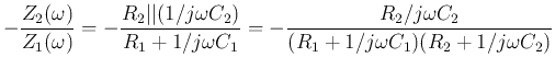
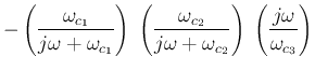
- Second Order Band-pass Filters:
We let
and get the FRF of this inverting amplifier as
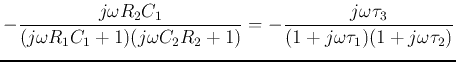
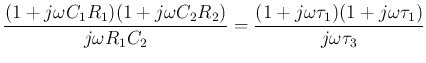
where
 ,
,
 ,
and
,
and
 .
.
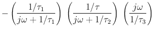
We assume both  and
and  are higher than
 , i.e.,
 , then
we have a band-pass filter, as can be seen in the Bode plot.
, then
we have a band-pass filter, as can be seen in the Bode plot.
For example, when
 ,
,
 , and
, and
 , the Bode plots are shown below:
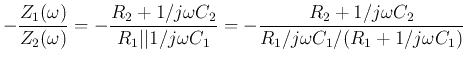
- Second Order Band-stop Filters:
If we swap  and
and  in the op-ammp circuit
of the band-pass filter, we get:
in the op-ammp circuit
of the band-pass filter, we get:
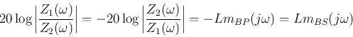
The log-magnitude of the Bode plot of this circuit is
We see that this is band-stop filter, and its log-magnitude is
a vertically flipped version of that of the band-pass filter
considered previously.