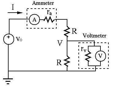
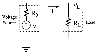
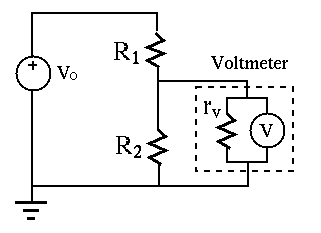
(b) A voltmeter can be modeled by an ideal meter (with infinite impedance) in parallel
with an internal (or input) impedance ![]() . To minimize the influnce of the voltmeter
on the circuit during the measurement, should
. To minimize the influnce of the voltmeter
on the circuit during the measurement, should ![]() be minimized or maximized?
be minimized or maximized?
(c) Calculate current ![]() and voltage
and voltage ![]() in the simple circuit below, assuming
in the simple circuit below, assuming
![]() ,
, ![]() and the measuring meters are not connected, i.e., the ammeter
is short circuit, the voltmeter is open circuit.
and the measuring meters are not connected, i.e., the ammeter
is short circuit, the voltmeter is open circuit.
(d) What is the reading on the ammeter with ![]() inserted in the circuit
as shown? Assume the voltmeter is not connected.
inserted in the circuit
as shown? Assume the voltmeter is not connected.
(e) What is the reading on the voltmeter with
![]() , connected
to the circuit as shown? Assume the ammeter is not connected.
, connected
to the circuit as shown? Assume the ammeter is not connected.


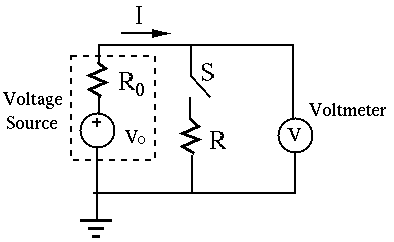
- When the battery is fresh, it is found
 when the switch is open
and
  when the switch is closed. Find the internal impedance
  .
.
- The same battery is tested one year later, and
 when the switch
is open and
  when the switch is closed. Find the internal impedance
 .
.


(As you see, the problems in these examples are solved in the notes. What you need to do is to read and understand these notes, and then write down and submit he results in your own way. (This is my way of making sure that you understand these materials but without spending too much time. You will see similar problems in future homework assignments.)