Next: About this document ...
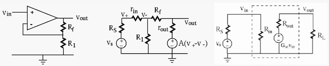
Find the input resistance  , output resistance
  and open-voltage gain
  of the inverting amplifier. (Read
and understand the derivation shown in the lecture notes.)
of the inverting amplifier. (Read
and understand the derivation shown in the lecture notes.)
Find the input resistance , output resistance
and open-voltage gain of the non-inverting amplifier,
and compare your results with those given at the bottom of
this page.
Express the output voltage  as a weighted sum of the four
input voltages
as a weighted sum of the four
input voltages
 :
:

Hint: Define
 , and apply KCL to
  and
and  to get two equations. Solve one of them for
  , substitute it into
the other equation, and then write as a function of all
four input voltages.
, substitute it into
the other equation, and then write as a function of all
four input voltages.
The algebraic summer can be generalized to have  inputs
  all connected through
  (
(
 ) to the inverting input
of the op-amp, and
) to the inverting input
of the op-amp, and  inputs
  all connected through
  (
(
 ) to the non-inverting input of the op-amp. Give
the general expression of the output as a function of all
) to the non-inverting input of the op-amp. Give
the general expression of the output as a function of all
 inputs in terms of all resistors
  resistors.
Derive the voltage gain (
 ) of the general Sallen-Key
fitler (HP or LP) in terms of the impedances
) of the general Sallen-Key
fitler (HP or LP) in terms of the impedances  through
  :
:
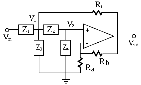
Derive the voltage gain (
) of the general Sallen-Key
fitler (HP or LP) in terms of the impedances through
and  ,
,  ,
,  .
.
(Hint: For simplicity, assume
 .
.
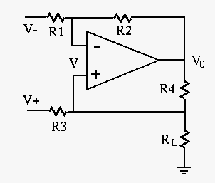
The circuit generates a constant current through the load, independent
of the load resistance  of the load. Give the expression of this
current
of the load. Give the expression of this
current  through as a function of the inputs and
and the resistances in the circuit, and show it is independent of .
Assume
through as a function of the inputs and
and the resistances in the circuit, and show it is independent of .
Assume
 .
.
Hint: recall the relationship between the current through and voltage across a diode and use the virtual ground assumption.
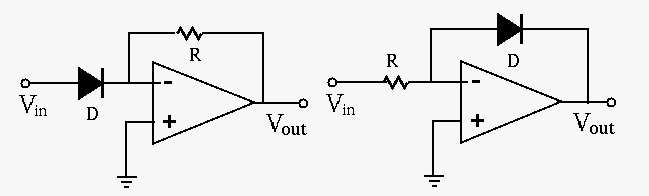
The current  through and voltage
  across a diode are related
by the following:
across a diode are related
by the following:

 and
and  are some parameters. The direction of the current
through the diode is indicated by the arrow of the symbol, and the
polarity of the voltage is plus on the arrow side and minus on the
other side. When
are some parameters. The direction of the current
through the diode is indicated by the arrow of the symbol, and the
polarity of the voltage is plus on the arrow side and minus on the
other side. When
 is large enough,
 .
.
Show that the output voltages of the exponential amplifier
(left) and logarithmic amplifier (right) are approximately an exponential
and logarithmic function of the input voltage  , respectively:

 and
and
 .
.