

Next: About this document ...
Up: compression
Previous: Predictive coding
The Joint Photographic Experts Group (JPEG) is the working group of ISO, International
Standard Organization, that defined the popular JPEG Imaging Standard for compression
used in still image applications. The counter part in moving picture is the ``Moving
Picture Experts Group" (MPEG).

JPEG compression is based on certain transform, either DCT or wavelet transform, due
to the essential properties of orthogonal transforms in general:
- Decorrelation of the signal;
- Compaction of its energy.
Check
this ACM page
for review of DCT vs. wavelet transform used for image compression.

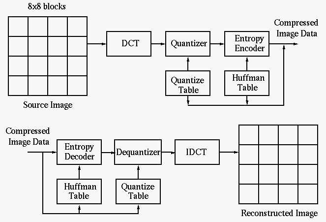
Here are the steps of
JPEG image compression
based on DCT:
- Divide the image to form a set of
 blocks and carry out
2D DCT transform
of each block. The computational complexity for 2D DCT of an
  image is
 , while the complexity of 2D DCT of all
  by
by  blocks of
image is
The larger the image size  , the more saving by sub-block transform. As adjacent
pixels are highly correlated, most of energy in an 8 by 8 block is concentrated in
the low frequency region of the spectrum (upper-left corner) and the rest transform
coefficients are very close to zero.
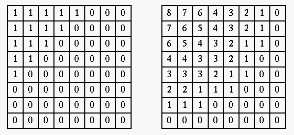
- Threshold all DCT coefficients smaller than a value T to zero, or alternatively,
low-pass (either ideal or smooth) filter the 2D DCT spectrum of each sub-image;

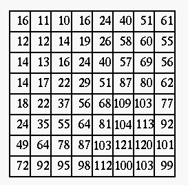
- Quantize remaining coefficients (convert floating-point values to integers).
First, the elements in each block are divided (element-wise) by the elements
in a quantization matrix Q:
where
and each of the resulting 8 by 8 elements is rounded to the nearest integer
(![$[x]$](img170.png) represents rounding
represents rounding  to the closest integer). At the receiving end,
the coefficients are recovered by:
Two observations can be made:

In general, assign smaller numbers around the top-left corner (low frequency
components) and larger ones around the lower-right corner (high frequency
components). The values are also heuristically determined according to
perceptual and psycho-visual tests.
- Predictive code all DC components of the blocks (as the DC components are highly
correlated);
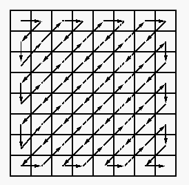
- Scan the rest coefficients in each block in a zigzag way (for higher probability of
longer consecutive 0's) to code them by run-length encoding;

- Huffman code the data stream;
- Store and/or transmit the encoded image as well as the quantization matrix.


Next: About this document ...
Up: compression
Previous: Predictive coding
Ruye Wang
2021-03-28


![\begin{displaymath}y(i,j)= \left[ \frac{x(i,j)}{Q(i,j)} \right] \end{displaymath}](img168.png)
![\begin{displaymath}Q=\left[ \begin{array}{ccc} ... & ... & ... ... & q_{ij} & ... \\
... & ... & ... \end{array} \right]_{8\times 8}
\end{displaymath}](img169.png)

