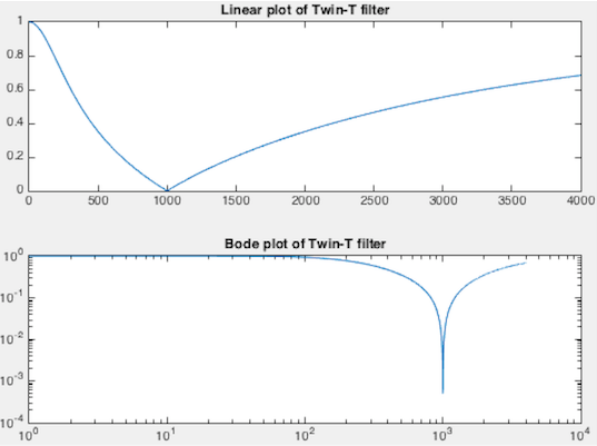
next up previous
Next: Wien bridge Up: ActiveFilters_sub Previous: The Sallen-Key filters

The Twin-T notch (band-stop) filter

The twin-T filter

TwinT.png

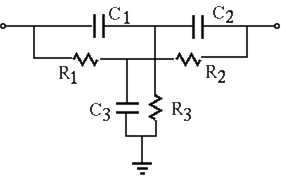
The twin-T network is composed of two T-networks:
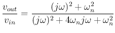
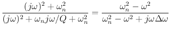
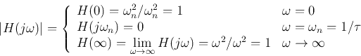
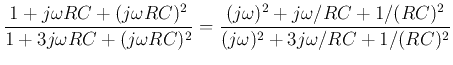
When the output is open-circuit, i.e., $Z_L=\infty$, the frequency response function of the twin-T network can be found to be (see here):

$\displaystyle H(j\omega)$ $\textstyle =$ $\displaystyle \frac{v_{out}}{v_{in}}
=\frac{(j\omega)^2+\omega_n^2}{(j\omega)^2+4\omega_nj\omega+\omega_n^2}$  
  $\textstyle =$ $\displaystyle \frac{(j\omega)^2+\omega_n^2}{(j\omega)^2+\omega_nj\omega/Q+\omega_n^2}
=\frac{\omega_n^2-\omega^2}{\omega_n^2-\omega^2+j\omega\Delta\omega}$  

where

\begin{displaymath}
\omega_n=\frac{1}{RC}=\frac{1}{\tau}
\end{displaymath}

$Q=1/4=0.25$ is the quality factor, and $\Delta\omega=\omega_n/Q=4\omega_n$ is the bandwidth of the filter. This twin-T network is a band-stop filter (notch filter) which attenuates the frequency $\omega_n=1/\tau$ to zero:

\begin{displaymath}
\vert H(j\omega)\vert=\left\{\begin{array}{ll}
H(0)=\omega_...
...ega^2/\omega^2=1 & \omega\rightarrow \infty
\end{array}\right.
\end{displaymath}

When this notch filter is used in a negative feedback loop of an amplifier, it becomes an oscillator.

TwinTPlots1.png

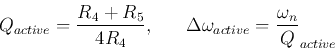
The active twin-T filter

The bandwidth $\Delta\omega=\omega_n/Q=4\omega_n$ may be too large for most applications due to the small quality factor $Q=1/4$. To overcome this problem, an active filter containing two op-amp followers (with unity gain $A=1$) can be used to introduce a positive feedback loop as shown below:

TwinTActive.png

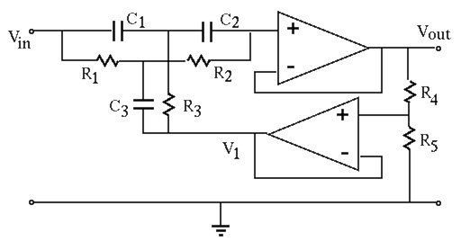
Now the common terminal of the twin-T filter is no longer grounded, instead it is connected a potentiometer, a voltage divider composed of $R_4$ and $R_5$, to form a feedback loop by which a fraction of the output $V_{out}$ is fed back:

\begin{displaymath}
V_1=\frac{R_5}{R_4+R_5}\;V_{out}=\alpha v_{out}
\end{displaymath}

where $\alpha=R_5/(R_4+R_5)$, i.e., $1-\alpha=R_4/(R_4+R_5)$.

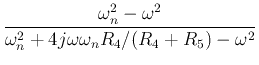
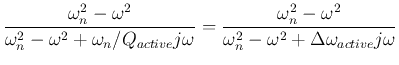
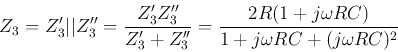
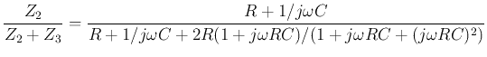
It can be shown (see here) that the frequency response function of this active twin-T filter is

$\displaystyle H_{active}(j\omega)$ $\textstyle =$ $\displaystyle \frac{\omega_n^2-\omega^2}{\omega_n^2+4j\omega\omega_n R_4/(R_4+R_5)-\omega^2}$  
  $\textstyle =$ $\displaystyle \frac{\omega_n^2-\omega^2}{\omega_n^2-\omega^2+\omega_n/Q_{active...
...
=\frac{\omega_n^2-\omega^2}{\omega_n^2-\omega^2+\Delta\omega_{active} j\omega}$  

where

\begin{displaymath}
Q_{active}=\frac{R_4+R_5}{4R_4},\;\;\;\;\;\;
\Delta\omega_{active}=\frac{\omega_n}{Q}_{active}
\end{displaymath}

are respectively the quality factor and the bandwidth of the active filter with feedback. By changing $R_4$ and $R_5$, the bandwidth $\Delta\omega_{active}$ can be adjusted. In particular,

The bridged T filter

If in the RCR T-network the vertical capacitor branch is dropped, i.e., $C=0$, the twin-T network becomes a bridged T network. Now we have $Z'_3=2R$, while the CRC T-network is still the same with $Z''_3=2(1+j\omega RC)/R(j\omega C)^2$, we get:

\begin{displaymath}
Z_3=Z'_3\vert\vert Z''_3=\frac{Z'_3 Z''_3}{Z'_3+Z''_3}
=\frac{2R(1+j\omega RC)}{1+j\omega RC+(j\omega RC)^2}
\end{displaymath}

The frequency response function of this bridged T network (a voltage divider) is:
$\displaystyle H(j\omega)$ $\textstyle =$ $\displaystyle \frac{Z_2}{Z_2+Z_3}=\frac{R+1/j\omega C}{R+1/j\omega C+2R(1+j\omega RC)/(1+j\omega RC+(j\omega RC)^2)}$  
  $\textstyle =$ $\displaystyle \frac{1/C}{1/j\omega C+2R/(1+j\omega RC+(j\omega RC)^2)}
=\frac{1}{1+2j\omega RC/(1+j\omega RC+(j\omega RC)^2)}$  
  $\textstyle =$ $\displaystyle \frac{1+j\omega RC+(j\omega RC)^2}{1+3j\omega RC+(j\omega RC)^2}
=\frac{(j\omega)^2+j\omega /RC+1/(RC)^2}{(j\omega)^2+3j\omega /RC+1/(RC)^2}$  

We let $\omega_n=1/RC$, and express both the numerator and the denominator in the canonical form as

\begin{displaymath}
H(j\omega)=\frac{(j\omega)^2+\omega_n j\omega +\omega_n^2}{(...
...a\omega_n j\omega }{\omega_n^2-\omega^2+\Delta\omega_dj\omega}
\end{displaymath}

where

\begin{displaymath}
\Delta\omega_n=\omega_n,\;\;\;\;\;\;\;\Delta\omega_d=3\omega_n
\end{displaymath}

are the bandwidth of the 2nd-order systems of the numerator and the denominator, respectively. We see that this is a band-stop filter.


next up previous
Next: Wien bridge Up: ActiveFilters_sub Previous: The Sallen-Key filters
Ruye Wang 2016-11-20