Next: About this document ...
Up: Appendix
Previous: Bode Plots of Components
First order circuits
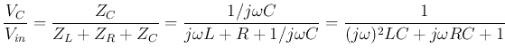
- Voltage
 across C is treated as output. According to voltage
divider rule, we have:
across C is treated as output. According to voltage
divider rule, we have:
where  .
.
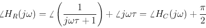
- Voltage
 across R is treated as output:
As  can be written as:
The first term is just  . Now the log-magnitude is:
The first term is the same as and the second plot is a straight line
with slope of 20 dB/dec. at
 , the first term is -3 dB and the
second is 0 dB. The phase plot is:
, the first term is -3 dB and the
second is 0 dB. The phase plot is:
In the plots below,  ,
,  rad/sec.
Define
 as the cut-off frequency, then when
 ,
we have
,
we have  , and
, and
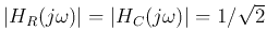 , i.e.,
  is the half-power point, where
  is -3 dB.
Second order circuits
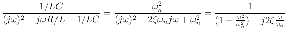
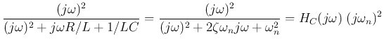
- Voltage across C is treated as output:
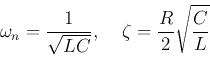
where
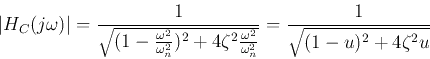
The magnitude is
where
 . When
 or
or
 , we have
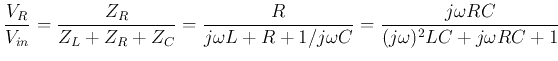
- Voltage across R is treated as output:
Now we have:
The log-magnitude of the second factor is a straight line with slope 20 dB/dec,
and at
, its value is
 . The phase is
 for all
  .
.
The denominator can be written as
 , which is minimized
when the imaginary part is zero, i.e,
, which is minimized
when the imaginary part is zero, i.e,
 . In other words, when
 ,
,
 reaches its peak value.
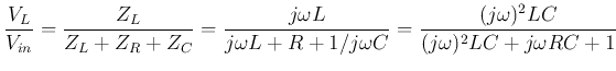
- Voltage
 across L is treated as output:
Now we have:
The log-magnitude of the second factor is a straight line with slope 40 dB/dec,
and at
, it's value is
 . The phase is
 for all .
In the following plots,  rad/sec and
  .
At
,
.
At
,
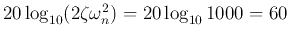 dB, and
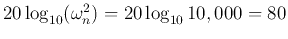 dB.
dB.
Example, a Band-pass filter:
where  ,
,  ,
,  .
.
Next: About this document ...
Up: Appendix
Previous: Bode Plots of Components
Ruye Wang
2019-05-07