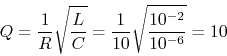
- Use Matlab to plot the frequency response functions (FRF) of the
RC first-order low-pass (voltage across C is the output) and high-pass
(voltage across R is the output) filters. Assume
 ,
,
 . Choose the range of frequency properly so that the
corner frequency is around the middle region of the plots.
. Choose the range of frequency properly so that the
corner frequency is around the middle region of the plots.
- Plot the linear gain and phase as a function of
 of
the two filters.
of
the two filters.
- Make the Bode plots (without using the built-in function Bode)
of both the gain (in log magnitude
 and
phase (between
and
phase (between  and
and  ) of the two filters (log scale in
frequency). The Matlab function semilogx can plot a function
) of the two filters (log scale in
frequency). The Matlab function semilogx can plot a function  with log scale in
  .
.
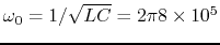
Solution: The first-order plots should be the same as those shown
in the lecture notes shown
here
with the only difference that the cornor (cut-off) frequency is at
 .
.
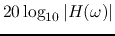
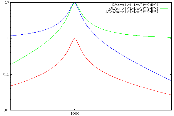
- Use Matlab to plot the frequency response functions (FRF) of the
RLC second-order low-pass (voltage across C as the output), band-pass
(voltage across R as the output), and high-pass (voltage across L as
the output) filters. Assume
 , , .
Choose the range of frequency properly so that the natural frequency
is around the middle region of the plots.
, , .
Choose the range of frequency properly so that the natural frequency
is around the middle region of the plots.
- Plot the linear gain and phase as a function of of the
three filters.
- Make the Bode plots (without using the built-in function Bode)
of both the gain and phase of the three filters (log scale in frequency).
Solution:
- In the circuit below,
 ,
,  ,
,  ,
and the sinusoidal voltage source is
,
and the sinusoidal voltage source is
 .
Find the complete voltage response
.
Find the complete voltage response  across
  and
and  after
the switch closes at
after
the switch closes at  .
.
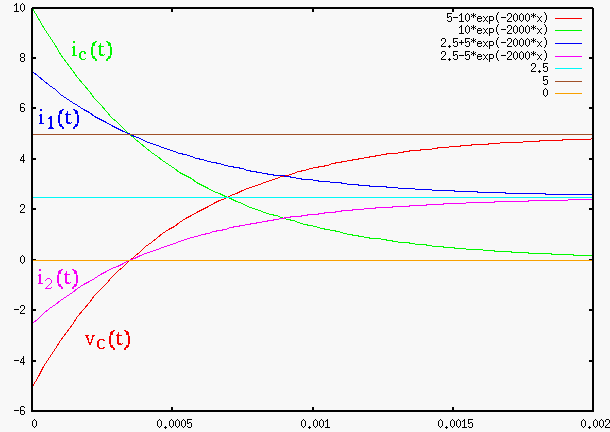
Solution:
- First find phasor representation of the voltage source:
 and the impedance of the capacitor:
 .
.
- Find
 :
:
- Find
- Find

Now we get:
- The RCL series circuit can be used as a filter when the voltage across
all three components is the input and the voltage across any of the
three components is treated as output. Find the resonant frequency
 (at which the output is maximized) in terms of the natural
frequency
(at which the output is maximized) in terms of the natural
frequency
 , when (1) voltage
  across C
is treated as output, and (2) voltage
across C
is treated as output, and (2) voltage  across L is treated as
output.
across L is treated as
output.
The frequency response functions  and
and  may have a peak, i.e.,
 for any
 , when
  is small enough, but it may not have such a
peak if is too large. Find the critical value
is small enough, but it may not have such a
peak if is too large. Find the critical value  so
that for any
so
that for any 
 and
and  will
have a peak at
will
have a peak at
 , but such a peak no longer exist when
 .
.
Solution: See
here
- An RCL series circuit composed of
 ,
,  and
and
 is connected to an input AC voltage
 .
.
- Find the quality factor
 and resonant frequency
  .
.
- Assume the voltage
 across
  is taken as the output voltage.
Find the bandwidth of the circuit. Also, use any software (e.g., Matlab)
to plot the ratio of the magnitudes between the output and input voltages
is taken as the output voltage.
Find the bandwidth of the circuit. Also, use any software (e.g., Matlab)
to plot the ratio of the magnitudes between the output and input voltages
 as a function of frequency .
- Assume the voltage across
 is taken as the output voltage.
plot the ratio
is taken as the output voltage.
plot the ratio  as a function of frequency .
- Assume the voltage across is taken as the output voltage.
plot the ratio
 as a function of frequency .
Solution:
- A series circuit composed of a capacitor and an inductor is to be
resonant at 800 kHz with voltage input. Specify the value of for the
capacitor required for the given inductor with
 and an internal
resistance
and an internal
resistance
 , and predict the bandwidth. Assume the capacitor
is ideal, i.e., it introduces no resistance.
, and predict the bandwidth. Assume the capacitor
is ideal, i.e., it introduces no resistance.
Solution:
As
 , and
, and
 , we
can find to be
, we
can find to be
Next find the quality factor:
then the bandwidth is
- Design a series circuit to be resonant at 800 kHz with a bandwidth
of 32 kHz. The inductor has and
. Find the
capacitance needed for the desired resonant frequency. In order to
satisfy the desired bandwidth, you may also need to include a resistor in
the circuit.
Solution: Based on the desired resonant frequency and bandwidth,
the quality factor needs to be
Since  , the resonant frequency is approximately
However, the quality factor of the parallel circuit is
twice the desired  , we have to double the resistance
  to
to
 to reduce by half.
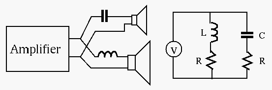
- The function of a loudspeaker crossover network is to channel
frequencies higher than a given crossover frequency
 into the
high-frequency speaker (``tweeter'') and frequencies below into
the low-frequency speaker (``woofer''). One such circuit is shown below.
Assume the resistances of the tweeter is
into the
high-frequency speaker (``tweeter'') and frequencies below into
the low-frequency speaker (``woofer''). One such circuit is shown below.
Assume the resistances of the tweeter is  and that of the
woofer is
and that of the
woofer is  , the voltage amplifier can be modeled as an
ideal voltage source, and the crossover frequency is
, the voltage amplifier can be modeled as an
ideal voltage source, and the crossover frequency is  .
Design the network in terms of and so that is the corner
freqnency or half-power point of each of the two speaker circuits. Give
the expression of the power
.
Design the network in terms of and so that is the corner
freqnency or half-power point of each of the two speaker circuits. Give
the expression of the power  and
and  of the speakers as a
function of frequency
of the speakers as a
function of frequency  and crossover frequency , and sketch them.
Assume the RMS of the input voltage is 1V.
and crossover frequency , and sketch them.
Assume the RMS of the input voltage is 1V.
Solution
The RMS voltage across the tweeter is
If  is at half-power point (
 ), the real and
imaginary parts of the denominator should be equal and we get
), the real and
imaginary parts of the denominator should be equal and we get
The RMS voltage across the woofer is
If is at half-power point (
 ), the real and
imaginary parts of the denominator should be equal and we get
), the real and
imaginary parts of the denominator should be equal and we get
The power plots: