

Next: About this document ...
E84 Home Work 7
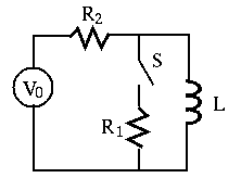
- Find the current
 through resistor
  after the
switch is closed at
  , assuming the input is a DC voltage and the
circuit is already in steady state before
  .
(Hint: current through an inductor cannot change instantaneously.)

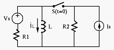
- In the circuit below,
 ,
,  ,
,  ,
,
 ,
,  . Assume before the switch is closed at
  , the
system is already stablized. Find current
  through
  and
voltage
  across
  .
.

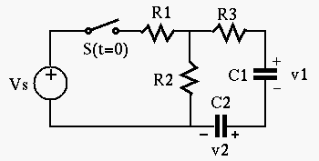
- In the circuit below,
 ,
,  ,
,  ,
,
 ,
,  ,
,  . Assume before the switch
is closed at
  , the system is already stablized. Find voltages
 and
and  across capacitors
  and
and  , respectively.
(Hint,
  and
and  are two capacitors in series with an equivalent
capacitance is
 .
.  and
and  have share the same
time constant
  .)
.)

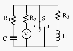
- In the circuit below,
 ,
,  ,
,  ,
,
 ,
,  ,
,  . The circuit is in steady state initially when
the switch is at position 2 (not connected). Find
  and
and  for the
following two independent cases:
- after the switch is changed to position 1 at
 ;
;
- after the switch is changed to position 3 at
 ;
;


Next: About this document ...
Ruye Wang
2008-03-19


 ;
;
 ;
;


