Next: About this document ...
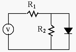
Solution: As the diode is forward biased, the voltage across it
is 0.7V, and the current through ![]() is
is
![]() ,
the current through
,
the current through ![]() is
is
![]() , and
, and
![]() .
.
Also, using Thevenin's theorem, we have
![]() ,
,
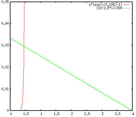
![]() , and then the linear equation
, and then the linear equation
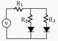
Solution: As the diode is forward biased, the voltage across it
is 0.7V. Assume the voltage in question is ![]() , then we have the following
equation:
, then we have the following
equation:
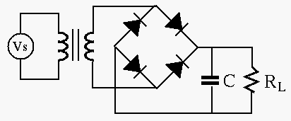
Solution: This is a full-wave rectifier circuit, which turns the
negative half cycle of the input to positive, so that the period of the
output is
![]() . The charge of the capacitor reduced during
this period is
. The charge of the capacitor reduced during
this period is
![]() . If the voltage across
the capacitor is dropped by less than
. If the voltage across
the capacitor is dropped by less than
![]() , its
capacitance has to be greater than
, its
capacitance has to be greater than
![]() .
.
The peak voltage of input is
![]() , the peak voltage
of the output is
, the peak voltage
of the output is ![]() . If the 1.4 V voltage drop across the two diodes
is considered small enough when compared with the required 12 V, then
the turn ratio of the transformer is
. If the 1.4 V voltage drop across the two diodes
is considered small enough when compared with the required 12 V, then
the turn ratio of the transformer is
![]() . Otherwise, the
the turn ratio is
. Otherwise, the
the turn ratio is
![]() .
.
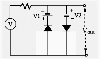
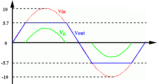
Solution: When ![]() is in the range from -5.7V to 5.7V, neither
of the two diode branches is conducting and no current is drawn from the
voltage source. As the result, the output is identical to the input.
When
is in the range from -5.7V to 5.7V, neither
of the two diode branches is conducting and no current is drawn from the
voltage source. As the result, the output is identical to the input.
When ![]() , the diode branch on the right is conducting and it
will hold the output at 5.7V. When
, the diode branch on the right is conducting and it
will hold the output at 5.7V. When ![]() , the diode branch on the
left is conducting and it will hold the output at -5.7V.
, the diode branch on the
left is conducting and it will hold the output at -5.7V.
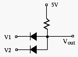
Solution: If at least one of the inputs is 0V, the corresponding diode is conducting and the output voltage is held to 0.7V. Only when both inputs are 5V, both diodes are cut off and draw no current from the voltage source. Since there is no voltage drop across the resistor, the output voltage is the same as the voltage source of 5V.
This circuit can be used to implement logic AND, i.e. only when both
input ![]() AND input
AND input ![]() are high (for true or logical 1), will the
output be high (true or logical 1). Otherwise the output is low (false
or logical 0).
are high (for true or logical 1), will the
output be high (true or logical 1). Otherwise the output is low (false
or logical 0).
| 0V | 0V | 5V | 5V | ||||
| 0V | 5V | 0V | 5V | ||||
| 0.7V | 0.7V | 0.7V | 5V |
