


Next: About this document ...
E84 Home Work 10
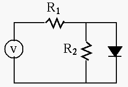
- The circuit shown in the figure contains a voltage source
 ,
two resistors
  and
and  , and a silicon diode.
Find the voltage
  across and the current
  through the diode.
Solve this problem in two different methods: (a) assume voltage
  (as the diode is always forward biased), and (b) use the graphic approach
to find the intersection of the load line and the diode equation:
Sketch the plot of the two curves and estimate the solution  at their intersection. (Note that you can assume
  and
and
 at room temperature 300K.)
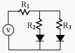
- The circuit shown in the figure contains a voltage source
 ,
three resistors
  ,
,  , and
, and  ,
and two silicon diode. Find the voltage across the two parallel branches.
(Hint: assume
  when the diode is forward biased.)
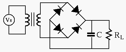
- The circuit shown in the figure is a converter (adaptor) based on
a full-wave rectifier, which gets an AC voltage input of 115V 60 Hz, and
produces a 12V DC output. The voltage variation or ripple of the output
should not exceed 5% when the load current is no more than 2A. Design
the converter in terms of the turn ratio of the transformer and the
value of the capacitor.
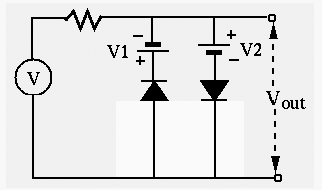
- The input voltage to the circuit in the following figure is
 . The two DC voltages are both 5V. Sketch the
waveform of the output voltage
  .
.
- Assume each of the input voltages
 and
and  takes one of
two values, either 0V or 5V. Find the output voltage
  in the
following combinations of three input:
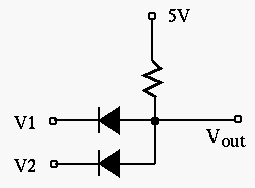


Next: About this document ...
Ruye Wang
2008-04-16


